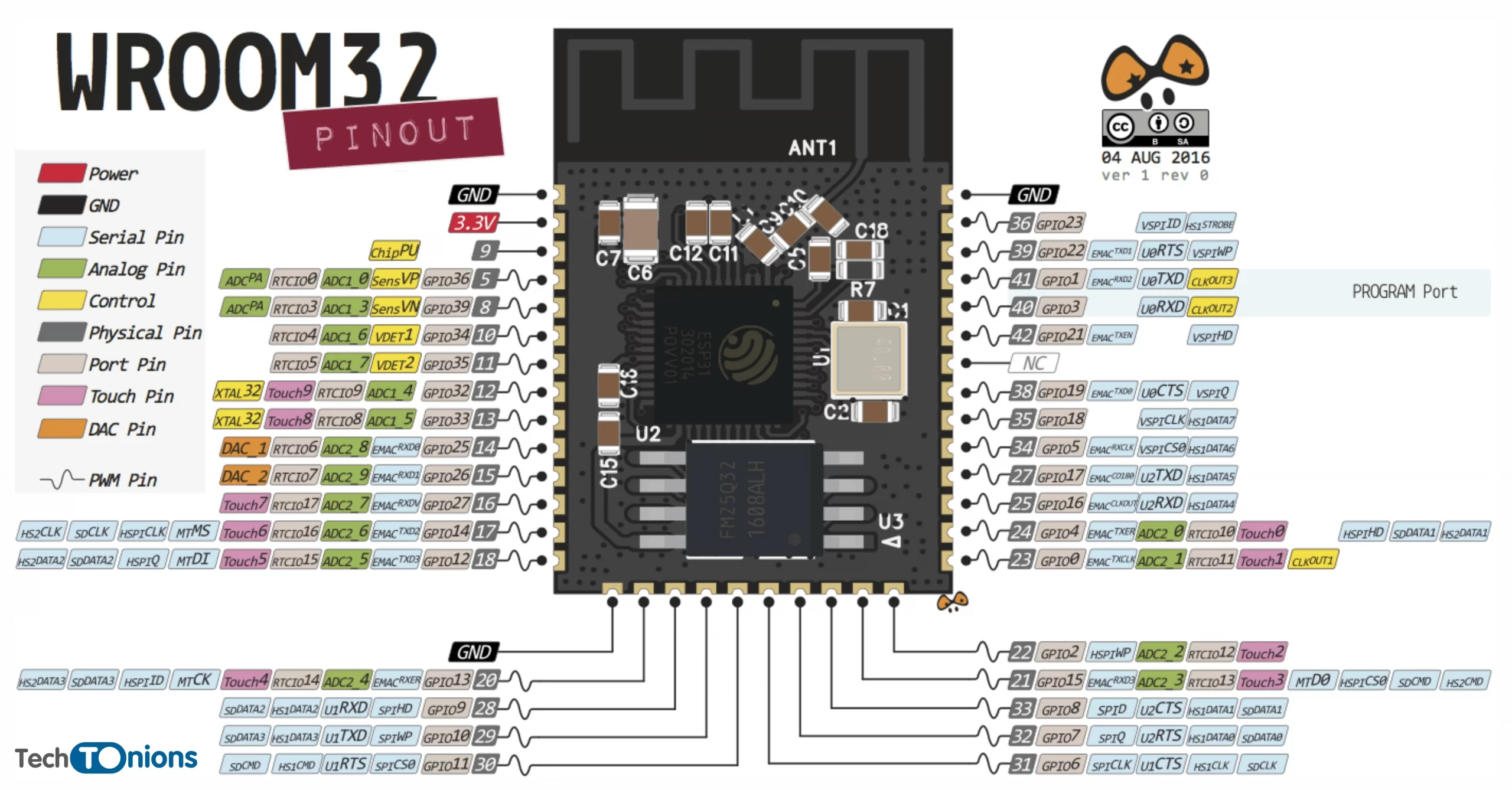
In the ESP32 pinout, if you count the pins on an ESP-WROOM-32 bar module, you will see that it has a total of 38 pins. Among these pins, including power, GND, reset, NC pins, etc., only 33 are GPIO pins. However, out of these 33 GPIO pins, only 27 are usable GPIO pins.
Not all GPIO pins will be accessible in all ESP32 development boards. Still, the numbering and the functionality of the GPIO remain the same among all boards.
All GPIO pins in ESP32 have multiple functionalities. A few of them are bootstrap pins, which we will discuss later. Therefore we need to take extra precautions while using ESP32 GPIO pins.
ESP32 Peripherals and Sensors
All ESP32 GPIO pins are multiplexed which means we can use individual GPIO pins for multiple functionalities.
Here is the list of all ESP32 peripherals:
- 3x UART interphase
- 3x SPI interphase
- 2x I2C bus
- 2x I2S bus
- 16x LED PWM channel
- 8x RMT channels (Infrared Remote Controller)
- 8x PCNT (Pulse Counter) channels
- 18x ADC ( Analog to Digital Converter)
- 2x DAC (Digital to Analog converter)
- 10x Touch Sensor
- Hall Effect Sensor
- 16x RTC GPIOs
- Interrupts
- Strapping GPIOs
- Input Only GPIOs
- Internal SPI Flash Pins
Among all listed ESP32 peripherals above the yellow marked are all static pins. There are predefined GPIOs for them that can utilize that peripheral.
Whereas green marked one can be assigned to any GPIO pin, we need to set them in our code. It is possible because of ESP32 internal GPIO multiplexing.
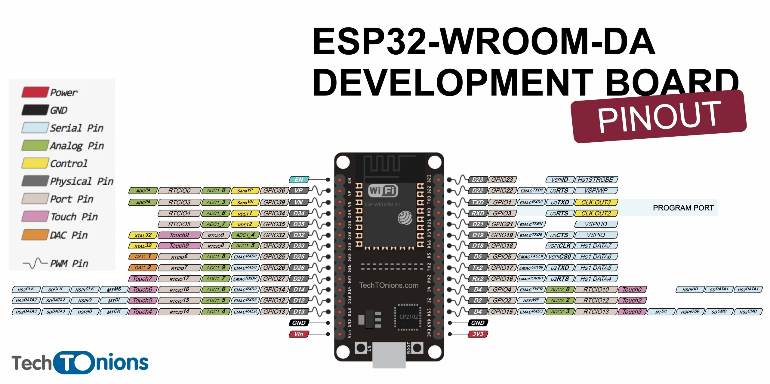
ESP32 WROOM Pinout
Below is the ESP32-wroom pinout of the ESP32-WROOM-DA development board. Furthermore, you will notice that there are GPIO pins that are already default assigned for UART, SPI, I2C, etc. But, you can always change them as per your project need.
ESP32 GPIO Pin Selector
Here is our easy-to-use ESP32 GPIO pin selector table. Moreover, it has all the listed GPIO pins exposed in most of the ESP32 development boards out there. This table represents all available GPIO pins suitable for output or input pins. Some pins are not ideal for your IoT project purpose, and a few of them are strapping pins, which we will discuss later on.
The pins highlighted in GREEN are OK to use as output or input pins. The ones highlighted in YELLOW are OK to use but need some extra precaution while using them, as it can cause some unexpected behavior to ESP32. also the RED ones are not recommended to be used as input or output pins.
Apart from this, we have added a check box to select the GPIO pins you will use for your project. It will help you properly choose GPIO pins without conflicting the same GPIO usage and warn you when you select the wrong pin.
| Checkbox | GPIO | Input | Output | Notes |
|---|---|---|---|---|
| 0 | Pulled Up | OK | Pulled LOW once while programming | |
| 1 | TX Pin | OK | Debug output at boot & WPU | |
| 2 | OK | OK | Connected to on-board LED & WPD | |
| 3 | OK | RX Pin | HIGH at boot & WPU | |
| 4 | OK | OK | WPD | |
| 5 | OK | OK | WPU | |
| 6 | X | X | Connected to the integrated SPI flash | |
| 7 | X | X | Connected to the integrated SPI flash | |
| 8 | X | X | Connected to the integrated SPI flash | |
| 9 | X | X | Connected to the integrated SPI flash | |
| 10 | X | X | Connected to the integrated SPI flash | |
| 11 | X | X | Connected to the integrated SPI flash | |
| 12 | OK | OK | Boot fail if pulled high & WPD | |
| 13 | OK | OK | WPD | |
| 14 | OK | OK | WPU | |
| 15 | OK | OK | WPU | |
| 16 | OK | OK | ||
| 17 | OK | OK | ||
| 18 | OK | OK | ||
| 19 | OK | OK | ||
| 21 | OK | OK | ||
| 22 | OK | OK | ||
| 23 | OK | OK | ||
| 25 | OK | OK | ||
| 26 | OK | OK | ||
| 27 | OK | OK | ||
| 32 | OK | OK | ||
| 33 | OK | OK | ||
| 34 | OK | X | Input only | |
| 35 | OK | X | Input only | |
| 36 | OK | X | Input only | |
| 39 | OK | X | Input only | |
Notes:
|
||||
Stick around with us if you want to know more insights on ESP32 Pinout.
ESP32 UART Interphase
ESP32 pinout has 3 hardware UART ports they are UART0, UART1, and UART2.
UART0
- Rx GPIO 3
- Tx GPIO 1
UART0 port is utilized for programming and debugging the ESP32 board. Later the port will be connected to an onboard serial to USB converter chipsets like CP2102 or CH3401 in most ESP32 development boards.
Note: UART0 pins are not changeable. We must take extra care while using GPIO 3 and 1 as the wrong usage can cause uploading errors.
UART2
- Default Rx GPIO 16
- Default Tx GPIO 17
UART2 pins are denoted as Rx2 and Tx2 in most ESP32 development boards as well as you can change the UART2 pins as per your need.
UART1
- Default Rx GPIO 9
- Default Tx GPIO 10
Not sure why ESP people have selected GPIO 9 and 10 for UART1. They are already connected to an internal SPI flash memory and therefore are not recommended to use.
Anyways you can always change the UART1 GPIO pins when needed.
ESP32 SPI Interphase
ESP32 has 4 SPI peripherals. They are SPIO0, SPIO1, SPIO2 and, SPIO3.
- SPI0 and SPI1 are used internally to access the ESP32's attached flash memory. Hence we can not use them.
- SPI2 and SPI3 are general-purpose SPI controllers, and they are referred to as HSPI and VSPI, respectively. They are available to use.
Below are the default HSPI and VSPI pins, which you can change according to your needs.
| SPI | MOSI | MISO | CLK | CS |
|---|---|---|---|---|
| VSPI | GPIO 23 | GPIO 19 | GPIO 18 | GPIO 5 |
| HSPI | GPIO 13 | GPIO 12 | GPIO 14 | GPIO 15 |
I2C Bus
ESP32 has two I2C controllers (also referred to as ports). Any GPIO pin can be set as SDA or SCL pin.
Default I2C pin in ESP32 Arduino core are:
- GPIO 21 (SDA)
- GPIO 22 (SCL)
I2S (Inter-IC Sound) Bus
I2S is a serial, synchronous communication protocol generally used to transmit audio data. it is a digital form of audio data.
Using I2S, we can read data from a digital MEMS MIC such as ICS43434 or play your favorite music using a MAX98357A I2S amplifier.
ESP32 contains two I2S peripherals I2S0 and I2S1. You can assign any GPIO pins for I2S.
It is possible to route I2S0 output directly to the DAC's (Digital-to-Analog Converter) output channels (GPIO 25 & GPIO 26) to produce direct analog output without using external I2S codecs.
LED PWM channels
ESP32 has 16 independent LED PWM channels that can be configured to generate PWM signals at a resolution of 16-bit. Any output pin can be configured to produce LED PWM signals.
Note: GPIO34 to 39 can not be used to output PWM signals as they are Input-only pins. Please continue reading to know more about them.
ESP32 RMT channels
It has 8 different RMT channels that we can configure to send and receive IR (infrared remote) control signals. RMT module can also generate or receive many other types of signals.
We can use any input or output GPIO pin for RMT. We will be covering RMT usage in future guides.
ESP32 PCNT(Pulse Counter) channels
ESP32 has a dedicated pulse counter is designed to count the number of rising and falling edges of an input signal.
It has 8 channels of PCNT that can be used for pulse counting. You can use any input GPIO pin for PCNT.
ADC (Analog to Digital converter)
The ESP32 pinout has 2 SAR (Successive Approximation Register) ADC are ADC1 and ADC2. Together they consist of 18 ADC input channels with 12 bits of resolution.
Not all GPIO pins can be used as ADC pins; the below table shows which GPIO belongs to which ADC channel.
| GPIO | ADC |
|---|---|
| GPIO 36 | ACD1_CH0 |
| GPIO 37 | ACD1_CH1 |
| GPIO 38 | ACD1_CH2 |
| GPIO 39 | ACD1_CH3 |
| GPIO 32 | ACD1_CH4 |
| GPIO 33 | ACD1_CH5 |
| GPIO 34 | ACD1_CH6 |
| GPIO 35 | ACD1_CH7 |
| GPIO 4 | ACD2_CH0 |
| GPIO 0 | ACD2_CH1 |
| GPIO 2 | ACD2_CH2 |
| GPIO 15 | ACD2_CH3 |
| GPIO 13 | ACD2_CH4 |
| GPIO 12 | ACD2_CH5 |
| GPIO 14 | ACD2_CH6 |
| GPIO 27 | ACD2_CH7 |
| GPIO 25 | ACD2_CH8 |
| GPIO 26 | ACD2_CH9 |
Note: ADC2 pins highlighted in YELLOW can not be used as ADC when WiFi is enabled. So if your project needs WiFi enabled all time, consider using ADC1.
DAC (Digital to Analog Converter)
ESP32 pinout has 2 DAC channels of 8-bit resolution. You can use it to convert an 8-bit digital signal to a linear analog output voltage.
You can use only the following two pins for DAC.
- DAC1 (GPIO25)
- DAC2 (GPIO26)
Capacitive Touch Sensors
ESP32 has 10 capacitive-touch sensing GPIO pins, and it can detect variations induced by touching or approaching the GPIOs with a finger or other objects. These pins can be easily utilized as a capacitive touchpad instead of traditional mechanical buttons.
All capacitive sensing GPIOs are listed below.
- T0 (GPIO 4)
- T1 (GPIO 0)
- T2 (GPIO 2)
- T3 (GPIO 15)
- T4 (GPIO 13)
- T5 (GPIO 12)
- T6 (GPIO 14)
- T7 (GPIO 27)
- T8 (GPIO 33)
- T9 (GPIO 32)
Hall Effect Sensor
Another sensor inside the ESP32 is the hall effect sensor. This inbuild hall effect sensor can measure the change in the magnetic field around the ESP32 module.
The hall effect sensor is not connected to any GPIO pins. It's inbuild and ready to use by just initializing it in code.
RTC GPIOs
RTC pins are not for general project usage. The pins connected to the RTC are known as RTC GPIO. They are connected internally to the "RTC" low-power and analog subsystem.
It consists of a ULP (ultra-low power) Co-processor, staying ON in deep sleep modes. And it consumes significantly less amount of power as it's designed for ultra-low power needs.
Therefore these RTC GPIO pins can be used as a wakeup source when ESP32 is in deep sleep mode. Below is the list of all RTC GPIOs.
- RTC_GPIO0 (GPIO36)
- RTC_GPIO3 (GPIO39)
- RTC_GPIO4 (GPIO34)
- RTC_GPIO5 (GPIO35)
- RTC_GPIO6 (GPIO25)
- RTC_GPIO7 (GPIO26)
- RTC_GPIO8 (GPIO33)
- RTC_GPIO9 (GPIO32)
- RTC_GPIO10 (GPIO4)
- RTC_GPIO11 (GPIO0)
- RTC_GPIO12 (GPIO2)
- RTC_GPIO13 (GPIO15)
- RTC_GPIO14 (GPIO13)
- RTC_GPIO15 (GPIO12)
- RTC_GPIO16 (GPIO14)
- RTC_GPIO17 (GPIO27)
Interrupts
All Input GPIOs can be used as Interrupts. Additionally, we can set an interrupt in different modes such as Rising, Falling, Change, Low, and High.
Note: Add a check condition inside your ISR callback in Arduino ESP32 core. There is some issue that it fires on false edge, especially when the mode is set to Falling. Check out here.
Strapping GPIOs
ESP32 Pinout has few strapping pins, the state of these pins, while reset, will decide whether the ESP32 will enter in Boot mode or normal mode. You can check out more on ESP32 strapping pin's here.
A summary of all strapping pin functions is shown in the below table.
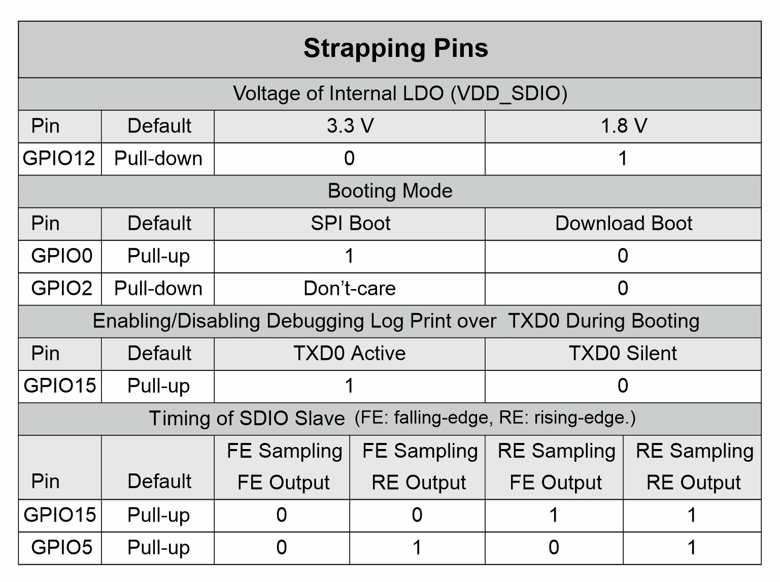
GPIO0
LOW - ROM serial bootloader for programming
HIGH - Normal mode.
GPIO2
GPIO2 must also be either left unconnected/floating or driven Low to enter the serial bootloader.
In normal boot mode (GPIO0 high), GPIO2 is ignored.
Extra attention is to be taken while using the GPIO2; if it's pulled up in your project, then you will be unable to program your ESP32 board.
GPIO12
LOW – flash voltage (VDD_SDIO) is selected 3.3V
HIGH – flash voltage (VDD_SDIO) is set to 1.8V
GPIO12 has an internal pull-down; therefore, if the pin is left floating, it will select by default 3.3v flash voltage.
ESP32 pinout development boards typically have a 3.3V internal flash. Therefore, if you accidentally pull up the GPIO12, the flash voltage is set to 1.8V, and the ESP32 will not boot up properly due to a lack of sufficient 3.3V for the flash memory.
GPIO15
LOW – Silences boot messages printed by the ROM bootloader.
HIGH – Normal output.
Since GPIO15 has an internal pull-up, unconnected = high = normal output. If you pull down the GPIO15 pin on boot up, the ESP32 will print and silence boot messages to the TXD0 pin (Serial monitor). However, this action may or may not cause problems, depending on what you have connected to GPIO15.
As you can see in the picture below, when ESP32 is reset and GPIO15 is disconnected, a boot message appears on the Arduino Serial monitor.
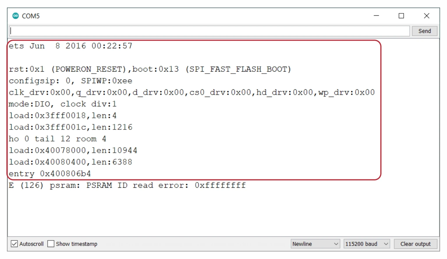
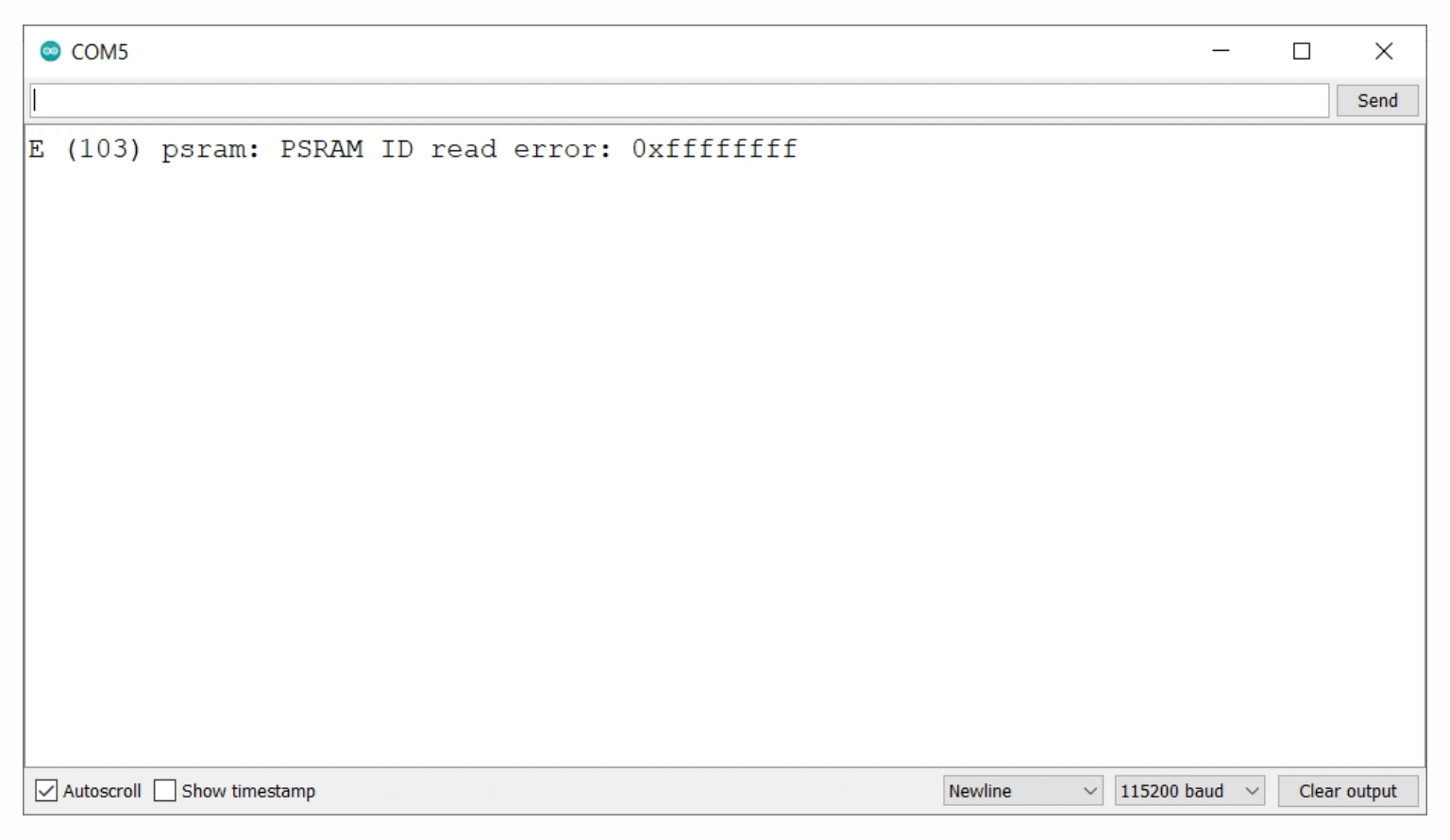
By connecting GPIO15 to GND, the boot message is no longer printed on reset.
Input Only GPIOs
GPIOs 34 to 39 are input-only GPIO pins. These pins can not be used as output pins, hence use them just for input purposes.
- GPIO 34
- GPIO 35
- GPIO 36
- GPIO 39
Note: Input-only GPIO pins also don't have internal pull-up resistors, so if you are going to connect buttons or similar to these pins, consider adding an external pull-up or down resistor.
Internal SPI Flash Pins
In ESP32 pinout, GPIO6 to 11 are connected to an internal SPI flash memory. In a few of the ESP32 development boards, these GPIO pins are exposed, but we do not recommend them in your project unless you are an ESP32 expert and you know what you are doing.
Don't use the below-mentioned GPIO pins.
- GPIO 6 (SCK/CLK)
- GPIO 7 (SDO/SD0)
- GPIO 8 (SDI/SD1)
- GPIO 9 (SHD/SD2)
- GPIO 10 (SWP/SD3)
- GPIO 11 (CSC/CMD)
Wrapping Up
We hope that this ESP32 pinout guide will help you select the right GPIO pins for your next ESP32 project. However, there is a complete table layout of each ESP32 pin if you are interested in learning more.
We tried to build this tutorial to help/guide us in developing more ESP32 based custom PCB projects.
If you have any more Ideas on the ESP32 pinout, do not forget to leave a comment below and If you are new to ESP32 development, we have some great writeups that you need to check out.
❑ Installing ESP32 in Arduino IDE
❑ Sending Messages and Images to Signal App from ESP32
Be sure to check out our informative learn posts to expand your knowledge on the topic!


This is awesome! Thank you for this!!!!
Thank you, Chase
Hi,
I connected to ESP32 pin12 to gnd with 30kOhm pull down resistor.
Will this be a problem for booting?
Otherwise, Is silencing the boot message an obstacle to boot?
Hii, Fatih
There is no problem with connecting the pull down resistor on ESP32 pin 12,
If you are connecting pull up there might be a problem you can check it out in the given table click here for more details.
This is awesome Tutorial and the best part is ESP32 GPIO Pin Selector Tool,
Thank you for this!!!!
TechTOnions.
Thank you, Parth