1. What is a PCB header connector?
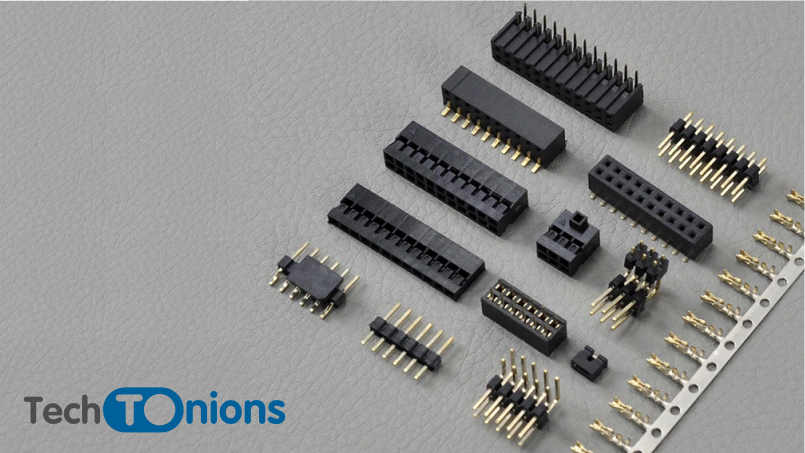
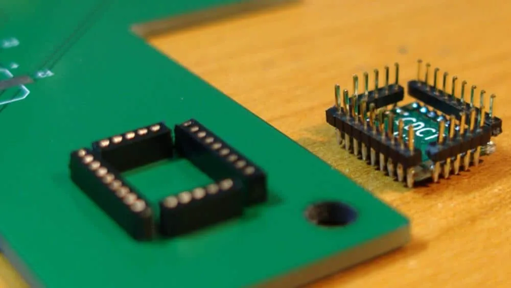
A PCB pin header connector consists of square pins shaped into insulating plastic material to create a male connector. These connectors are typically manufactured with one or two rows, although some designs offer three or more rows. Socket headers are often mated with pin header connectors to provide a reliable and cost-effective board-to-board connection.
They are frequently sold in long strips (generally 36, 40, and 50 pins) and can easily be cut apart to the needed amount of pins. Several pin dimensions are accessible to minimize labor during PCB assembly. Male connectors are typically identified as pin headers since they’re simple rows of pins. Female connectors are also known as plugs, receptacles, or even plugs.
2. HEADER Applications
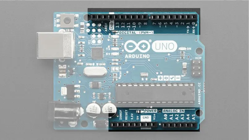
Pin headers, box headers, and connectors are utilized in a wide range of industries such as video, lighting, portable devices, telephone service, electronic goods, industrial automation, healthcare, and energy, among others.
You may utilize headers in conjunction with jumpers to construct semi-permanent input devices.
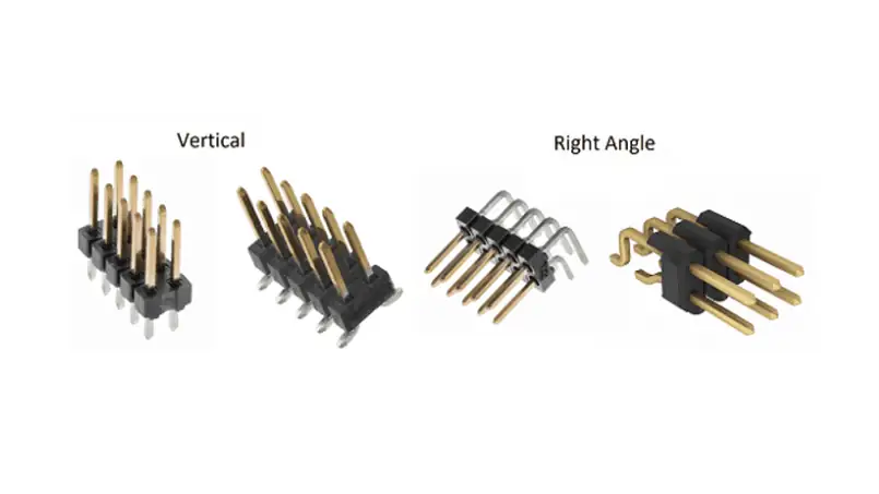
3. PCB Header Orientations
The orientation of a PCB Pin header depends on the specific header and its intended use. Generally, you can arrange the pins in a straight line or in a right-angle or L-shaped configuration. When designing a PCB PIN layout, it’s important to carefully consider the orientation of the header pins in order to ensure that they will mate properly with the corresponding connector.
Depending on their design and application, manufacturers orient header connectors in different ways. The most common orientations are:
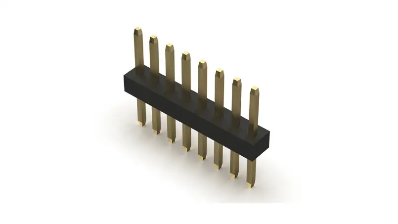
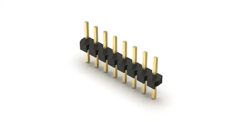
- Straight: The pins of the header connector arranged in a straight line and perpendicular to the PCB. Determining the orientation becomes possible when the header is at the edge of the PCB or when it is connected to a straight-oriented connector
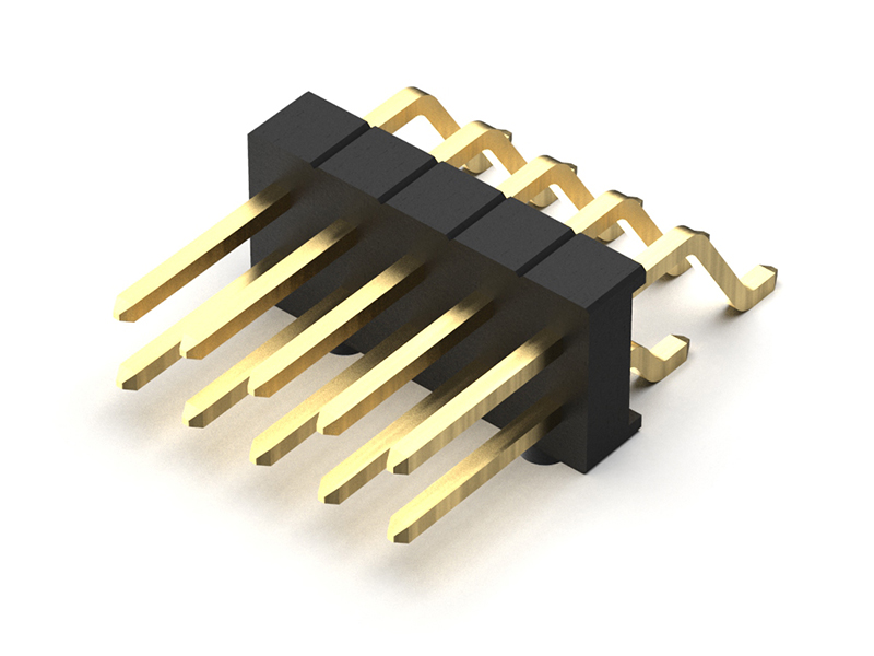
- Right-angle: A right-angle configuration arranges the pins of the header, enabling the connector to mount parallel to the PCB surface. This orientation is a common choice when space is limited, and the mating connector is also oriented at right angles.
Each orientation has advantages and drawbacks whereas a horizontal orientation allows for placing more components on the PCB. While conserving the device’s space the range of the Header is restricted
4. Different kinds of PCB Header
PCB headers are used to connect electronic components on printed circuit boards (PCBs). There are different kinds of PCB headers available in the market, each with its unique characteristics and uses. Some of the most common types of PCB headers are:
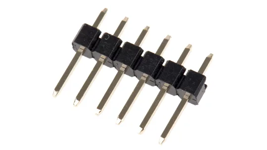
- Pin headers: PCB headers, which consist of a row of pins onto the PCB, are the most fundamental type. They come in various sizes, including straight and right-angled configurations.
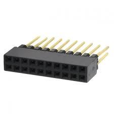
2. Socket headers: Socket headers are used to connect wires or other components to a PCB and They consist of a socket with a row of pins that can be soldered onto the PCB.
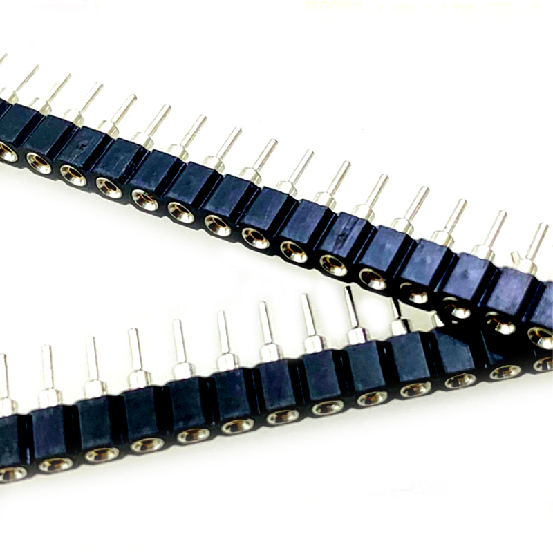
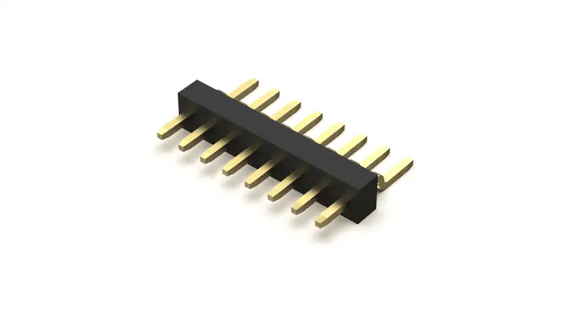
3. Header Strip(Machine Round): High quality gold plated breakaway strip with round male contacts on both sides. It consists of a row of 2.54mm male pins to fit into a female pin header, creating a secure and reliable connection.
NOTE: When using male machine rounded pins, which are typically connectors or pins with exposed prongs, you would need to connect them to a female machine rounded pin header.

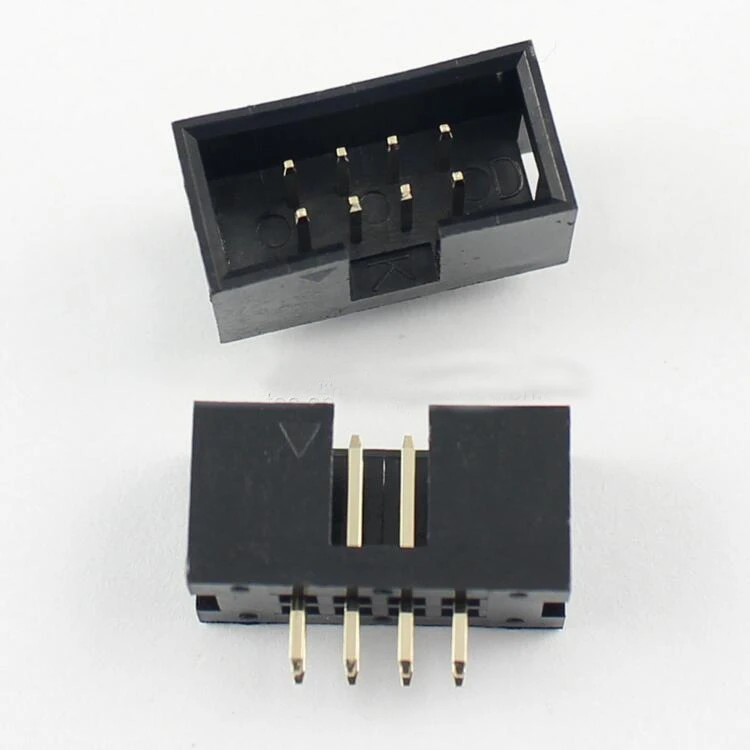
4. Box headers: These PCB headers have a rectangular shape where a higher number of pins connected also They are available in different sizes and can be straight or right-angled.
Here we are going to talk about the Types of Pin headers:
1. Based on GENDER:
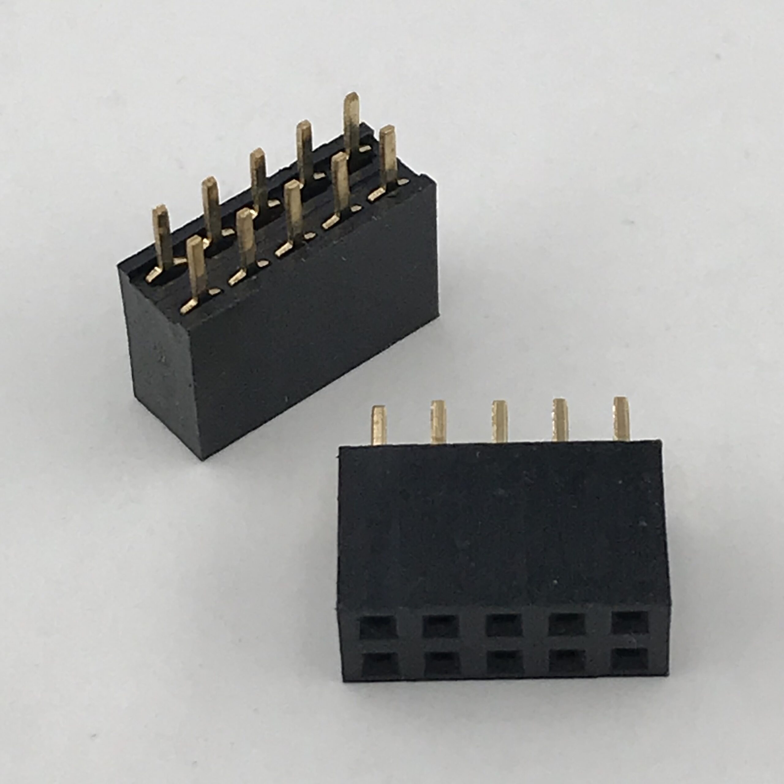
PCB Pin Header connectors are classified as male and female. Basically, a male connector known as a plug has a stable pin for a connector, and a female connector, also known as a jack, has a central conductor with a hole inside to accept the male pin.
2. BY PITCH
There are multiple choices of standard pitch options including 1.00mm, 1.27mm, 2.00mm, and 2.54mm.

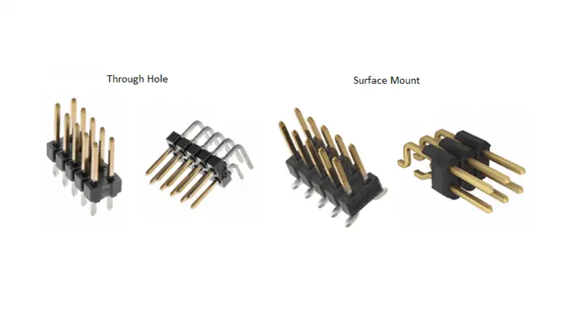
3. BY PCB Mount type:
In the SMD, the soldered edge of the pins is able to bend at a 90 ° angle SMD headers are modified switching between one side or another. whereas pins on dual-row SMD headers are easily bent outwards. For the easiness of the assembly process, the THD version is commonly selected When pin headers are not required.
4. PCB Orientation:
90° Angle, Motherboard to Daughterboard – one connector is vertical, the other horizontal.
180° Angle, Edge-to-Edge , both connectors horizontally oriented.
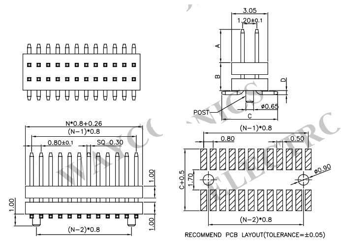
5. PCB Header Dimension
PCB Pin header connector dimensions typically include the number of pins, pitch (distance between pins), and overall height. The number of pins can range from just a few up to several hundred, depending on the specific application. Pitch can vary as well, with common values including 2.54mm, 1.27mm, and 1.00mm. The overall height of a header is also an important consideration, as it can affect the clearance required between the PCB and any components or enclosure it will be installed in.
Dimension Layout For 1.00mm:
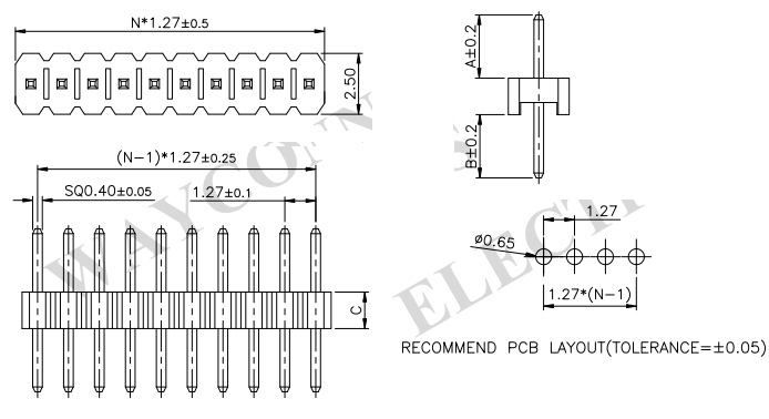
Dimension Layout For 1.27mm:
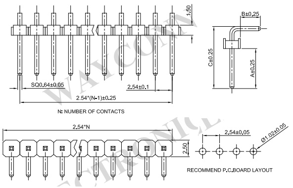
Dimension Layout For 2.54mm:
6. Conclusion
In conclusion, PCB pin header connectors are widely used in electronic devices and circuit boards to provide a secure and reliable connection between the PCB and external components. These connectors consist of a male or female connector with a series of pins arranged in a row inserted into corresponding sockets or receptacles.
PCB pin header connectors are available in various sizes, pitches, and orientations, allowing for customization and flexibility in design. They are designed to withstand high temperatures, shock, and vibration, making them suitable for use in harsh environments.