Table Of Contents :
- Jumbo 16×2 LCD Overview
- I2C LCD Adapter
- I2C LCD Display Pinout/Connections
- Connect I2C Jumbo LCD to Arduino Board
- Requirement – Installing Arduino IDE
- Installing I2C LCD Library In Arduino IDE
- Finding the I2C Address
- Hello World In Jumbo LCD
- How It Works
- Wrapping Up
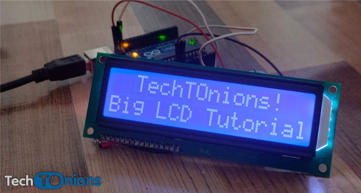
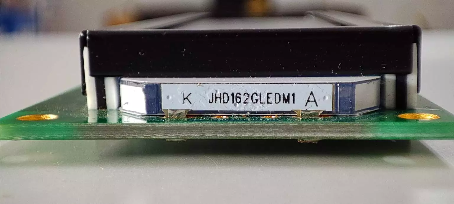
Jumbo 16×2 LCD Overview
The LCD that we will be using in this tutorial is from the JHD162G series. This display has 16×2 characters, but the character size is bigger than the standard 16×2 LCD.
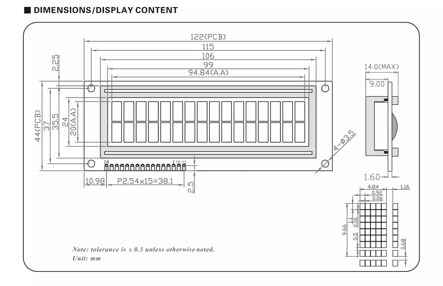
Have a look at the dimensions of this display.
As per the datasheet, the typical current consumption of this 16×2 LCD display is around 1.2mA, and the max current of 3mA.
Have a look at the display electrical specifications.
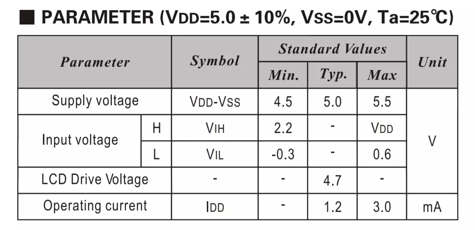
This display works on a 5v logic level; therefore, if you want to control it with a 3.3v logic level controller such as ESP32, then you need to use a logic level shifting circuit in between. You can learn more about level shifting here.
Don’t worry if you want to integrate this jumbo LCD into your existing LCD-based project, as there is no need to change your project code.
The controlling logic is the same for this bigger display; therefore, all LCD-based Arduino libraries will support this LCD display.
Apart from that, there is a slight change in the pinout of this display. The display pins are at the bottom part of the LCD.
Here is the pinout of this jumbo LCD display.

I2C LCD Adapter
For this project, we will be using an LCD I2C extender board. So that it requires only two pins for controlling the LCD, and it will simplify the overall wiring that is needed.
We are using a PCF8574 based I2C based 8-bit GPIO extender board. This board converts I2C data into parallel data required by the LCD.
We have traced the pinout of this board as per the LCD display.
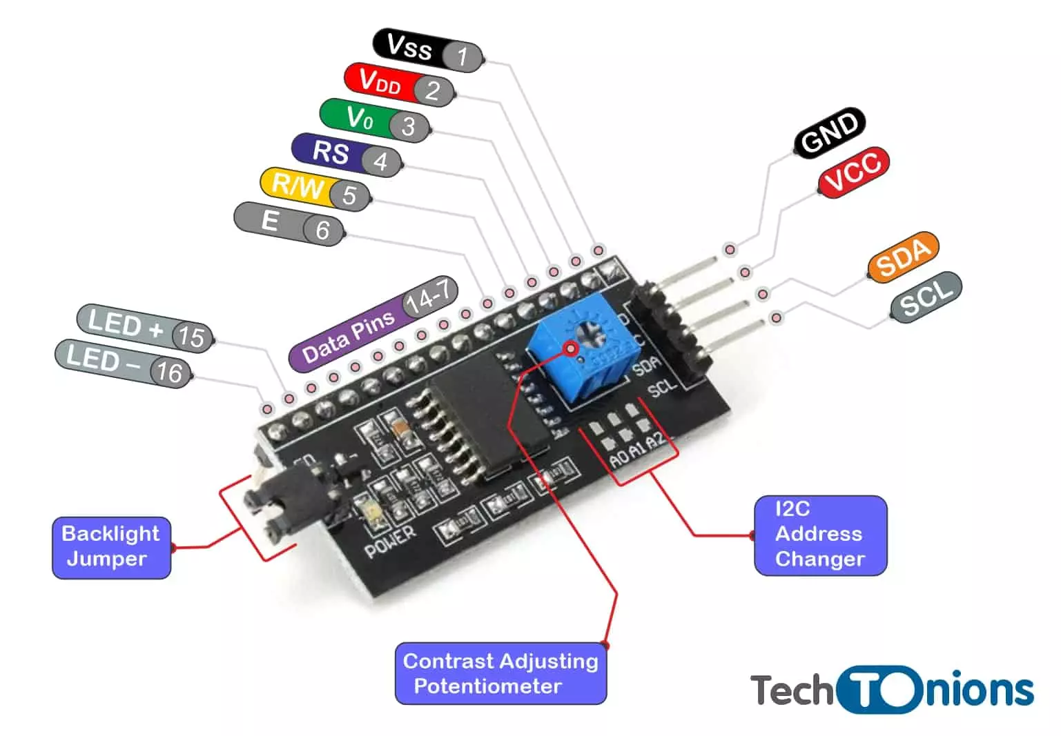
If you want to control the display backlight brightness, then you can remove the backlight jumper. And apply the external supply to LED pins.
I2C LCD display Pinout/Connections
First, we need to connect our LCD with the I2C extender. Here is the connection diagram for doing so.
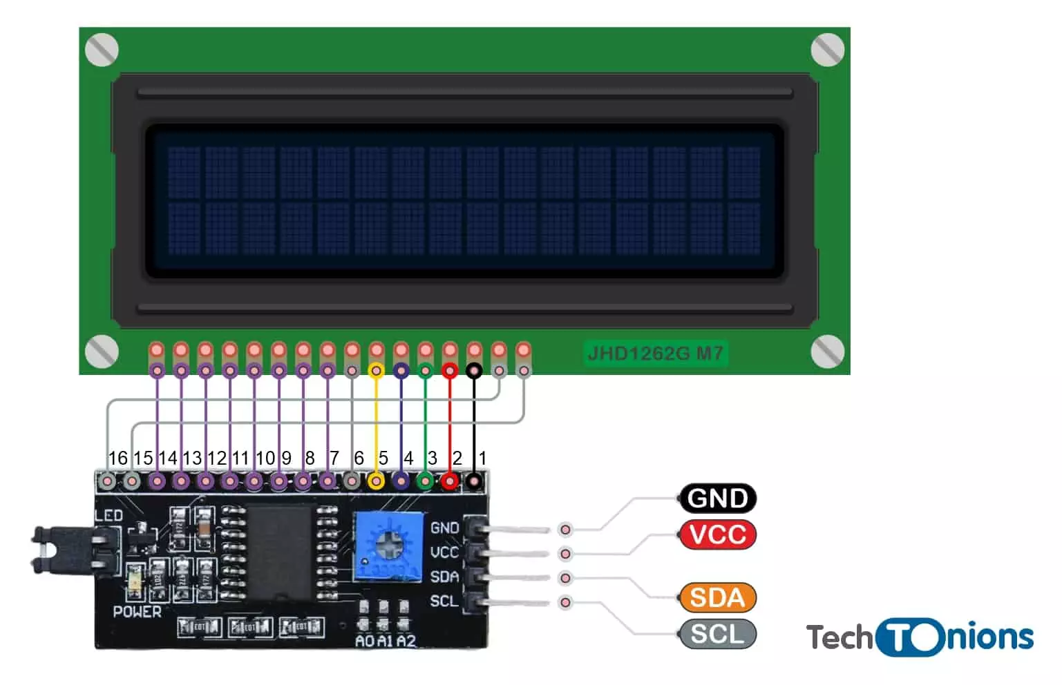
GND is a ground pin and should be connected to the ground of Arduino.
VCCsupplies power to the module and the LCD. Connect it to the 5V output of the Arduino or a separate power supply.
SDA is a Serial Data pin. This line is used for both transmit and receive. Connect to the SDA pin on the Arduino.
SCLis a Serial Clock pin. This is a timing signal supplied by the Bus Master device. Connect to the SCL pin on the Arduino.
As we observed, there is a slight change in the pinout between the jumbo LCD and I2C extender. In jumbo LCD, LED+ and LED- pin are at different locations; therefore, we must make minor modifications while connecting the I2C extender to the LCD.
Please stick around and follow along with us.
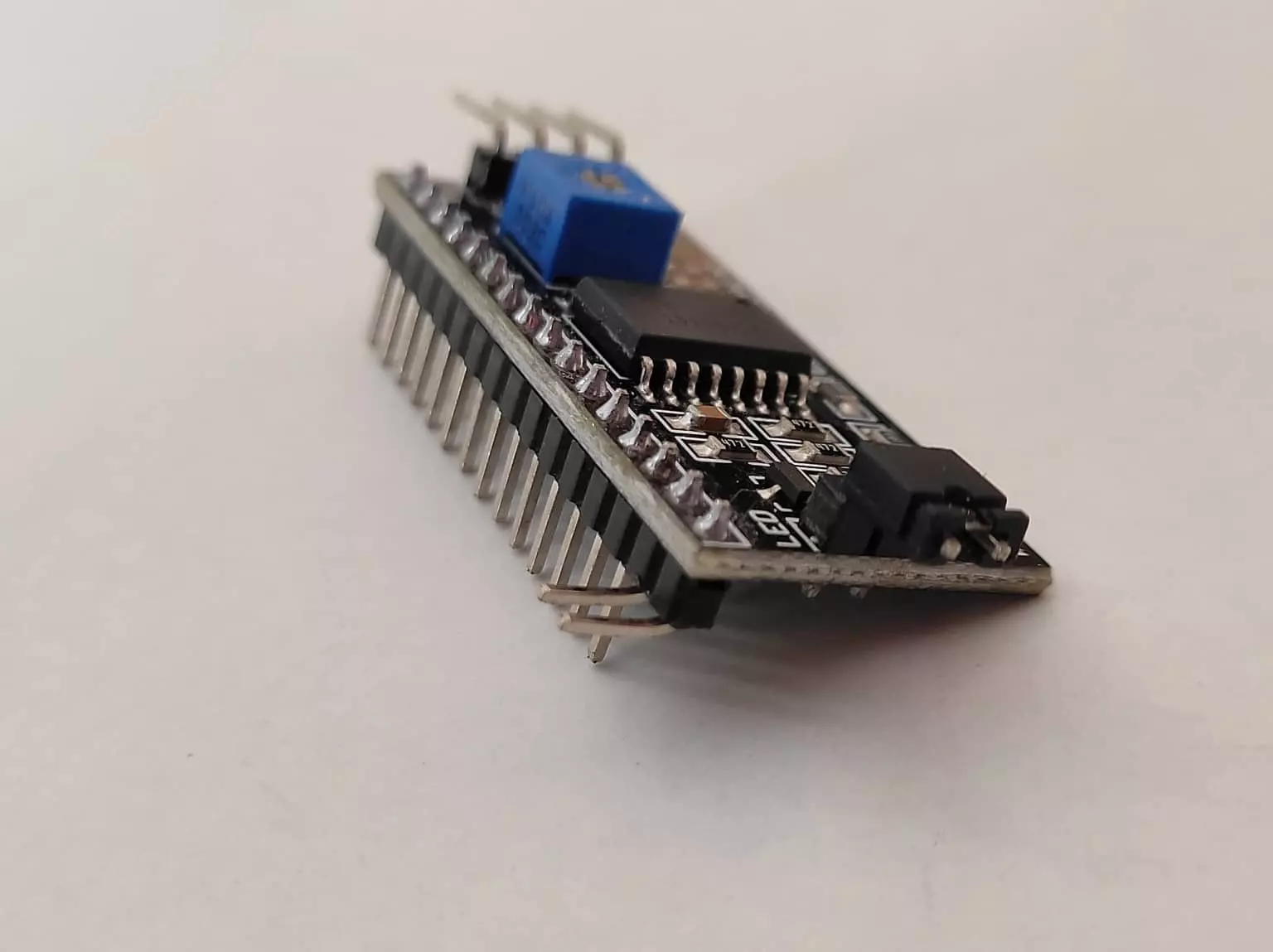
The first step will be to bend LED input pins on the extender to 90 degrees. Grab a plier or similar tool and bend the last two pins on the extender.
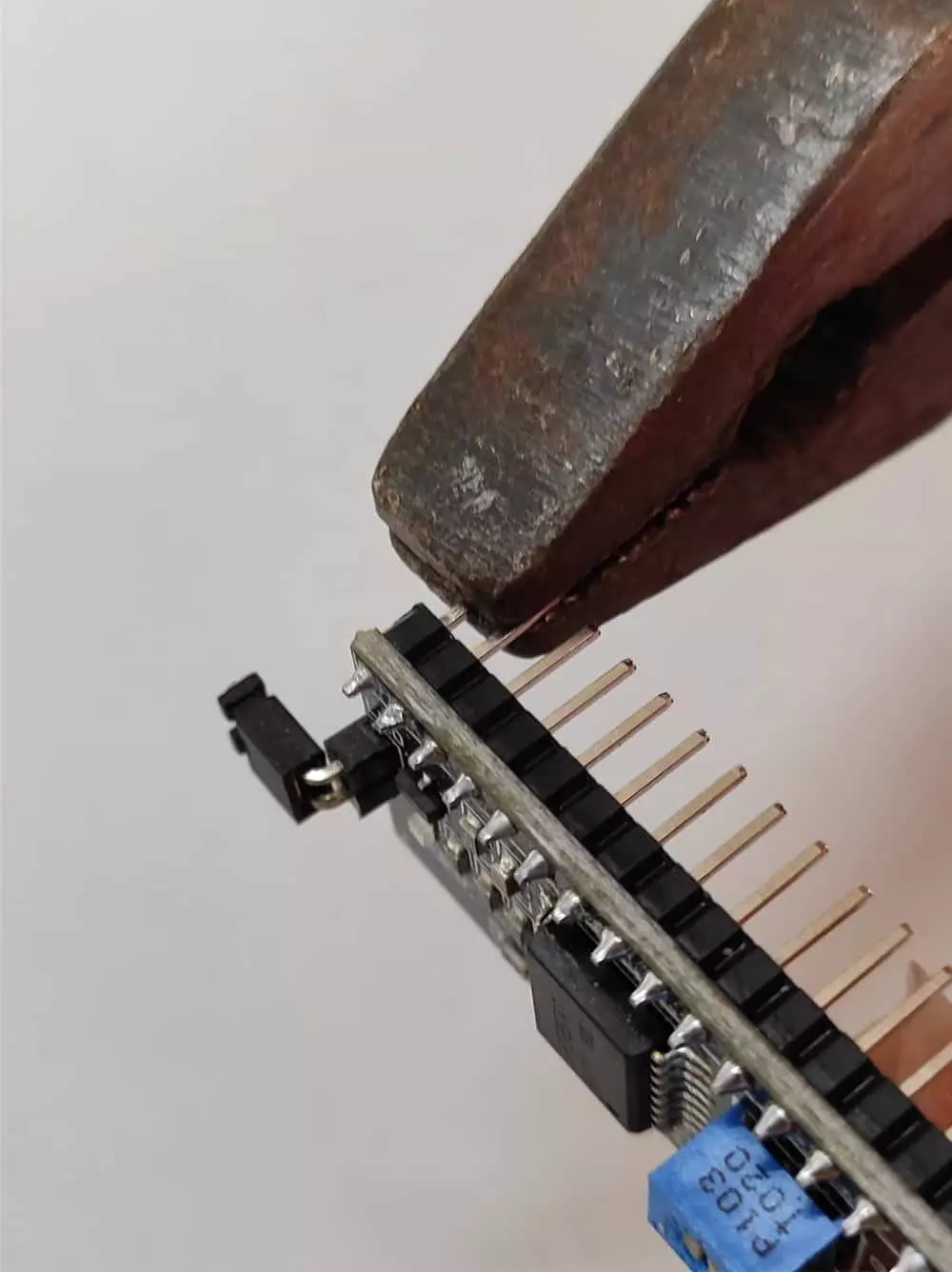
Once pins are bend, then the extender should look like this.
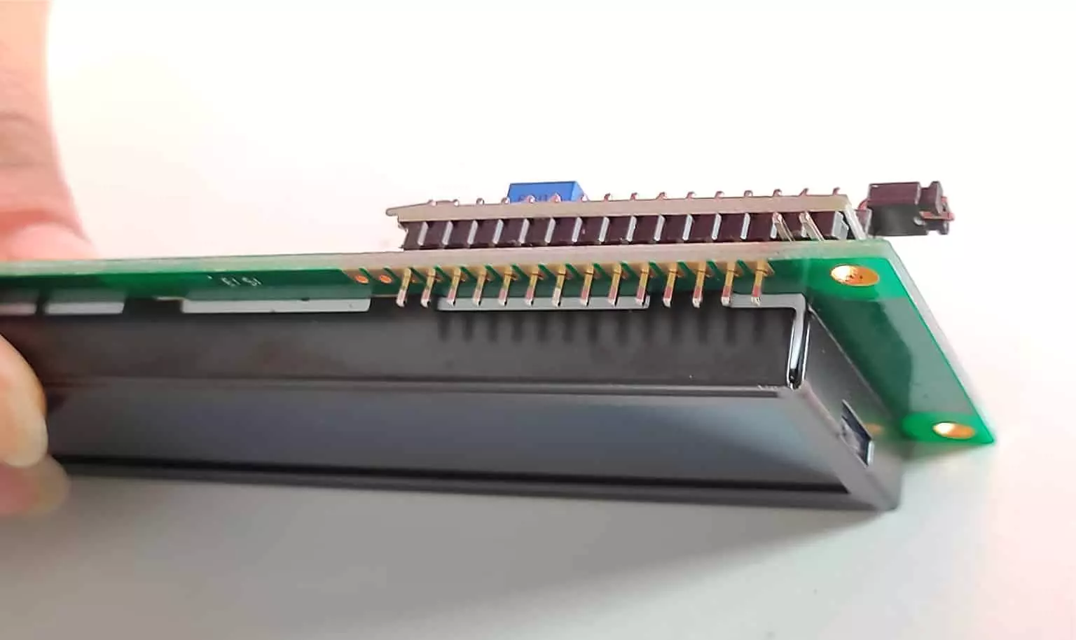
Now insert the extender from the backside of the LCD such that 2 bend pins will be the first, and it will not be in contact with LCD pins as of now.
We know it’s a little confusing therefore adding few images.
It should look like this after inserting the extender module with the LCD.
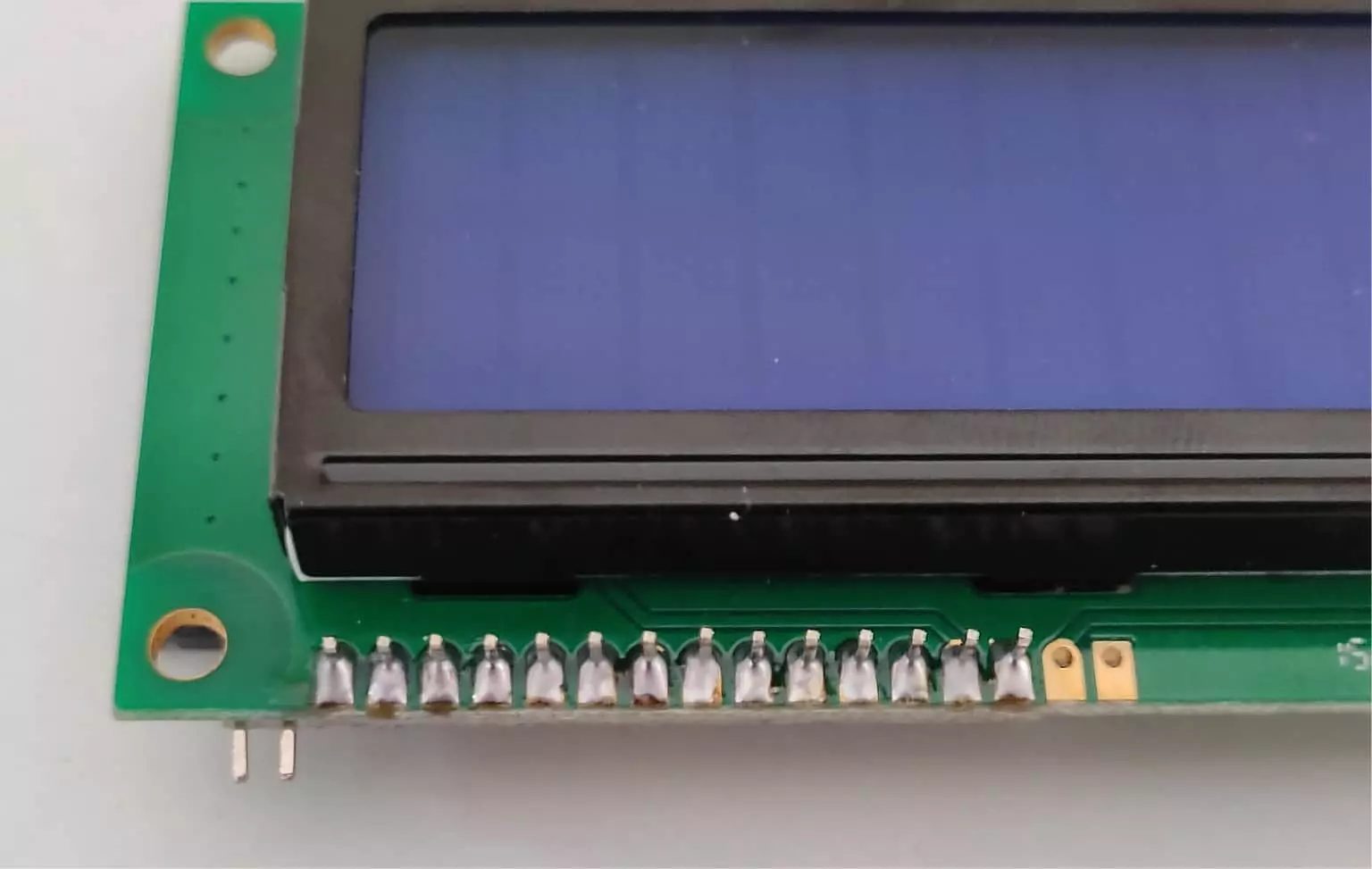
Once you are satisfied with the connection, then start soldering the extender pins to the LCD.
Once soldering is done, it should look like this.
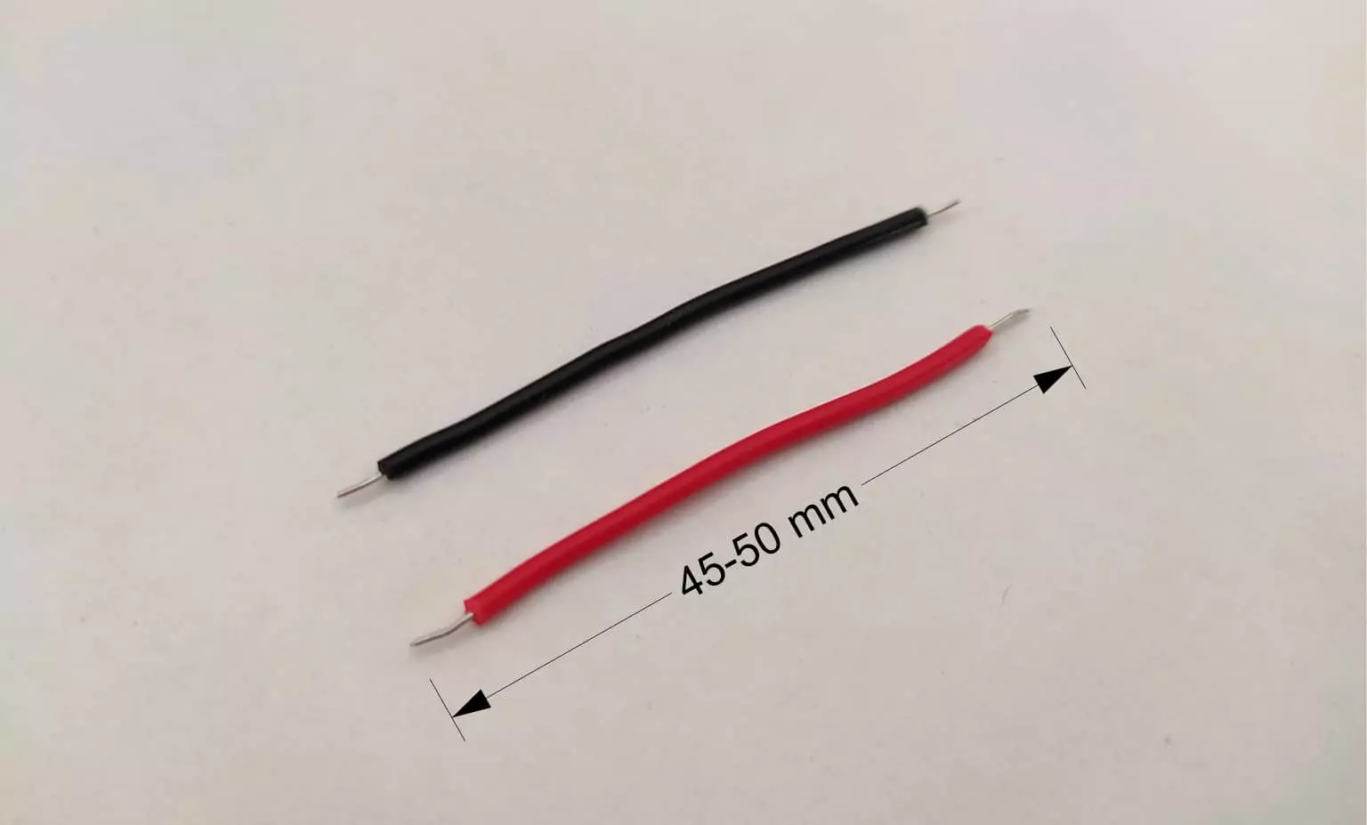
Now, cut two wires of 45-50mm long. We have chosen Red, and Black colored wire here to represent LED+ wire as Red and LED- as Black. You can select any color of your choice.
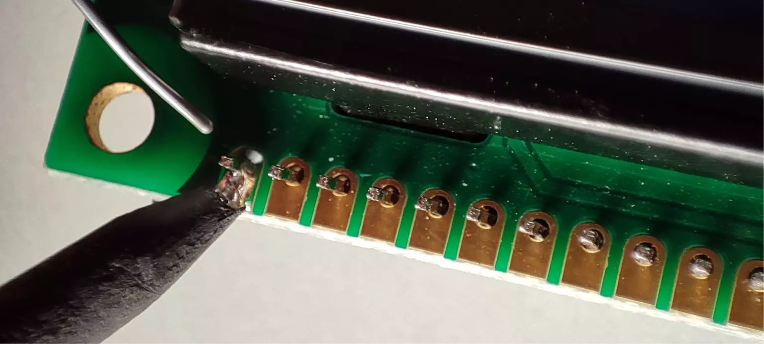
First, let’s connect the black wire to the LED- pin of the LCD. Insert the black wire in PIN 16 of the LCD.
Solder that wire to that pin.
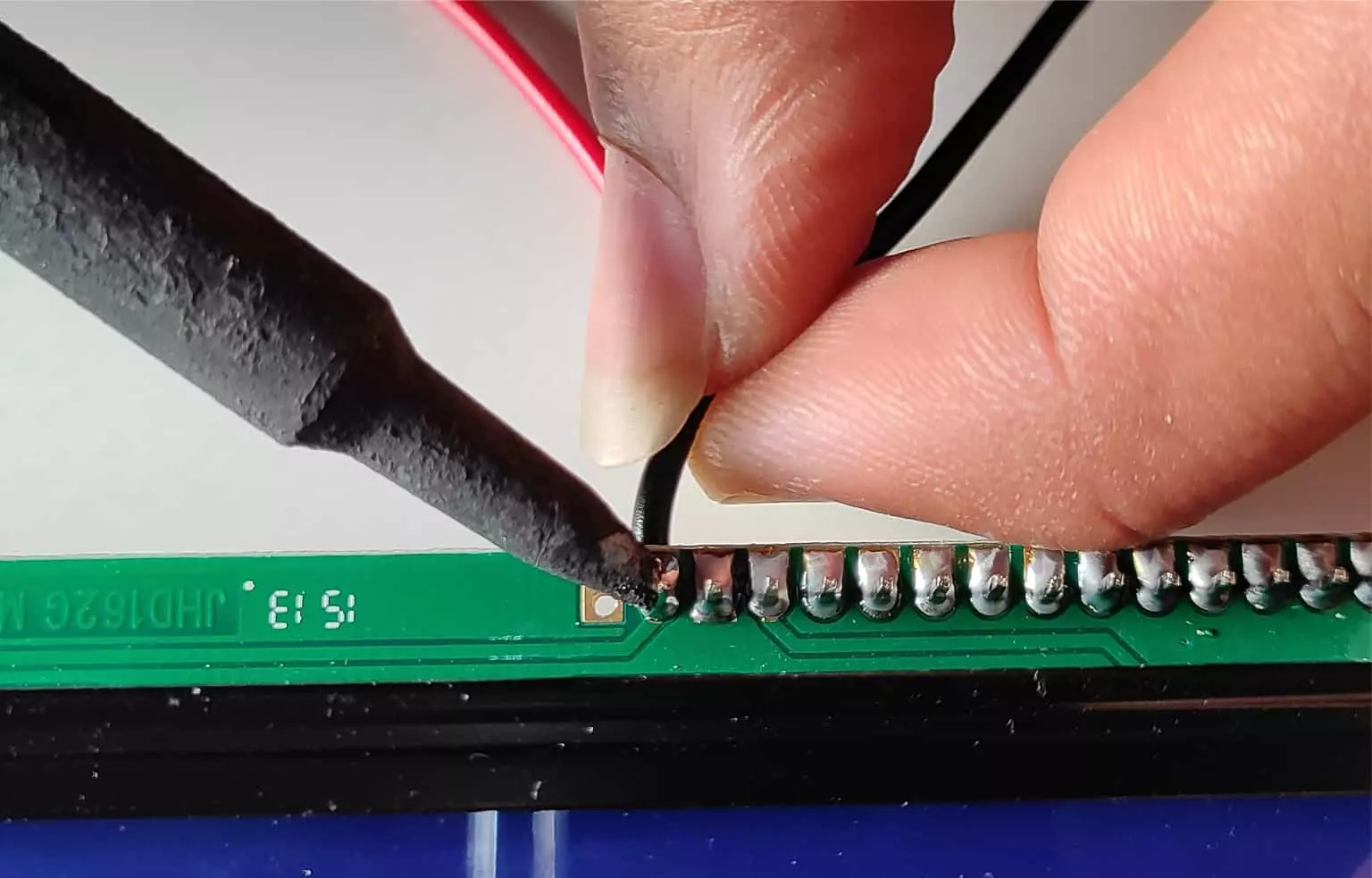
Now, connect the red wire to the LED+ pin of the LCD. Right next to the LED- pin.
Solder the Red wire also to the LCD similar to the black one.
Now it should look like our LCD has two small antennas. I was kidding!

Now, apply solder to both ends of the wires to connect easily to another end of the I2C extender board.
Similarly, apply a little solder to bend the pins of the extender board.
Now, solder the red wire to the LED+ pin of the I2C extender board.

Last we need to solder the black wire to the LED- pin of the I2C extender board.
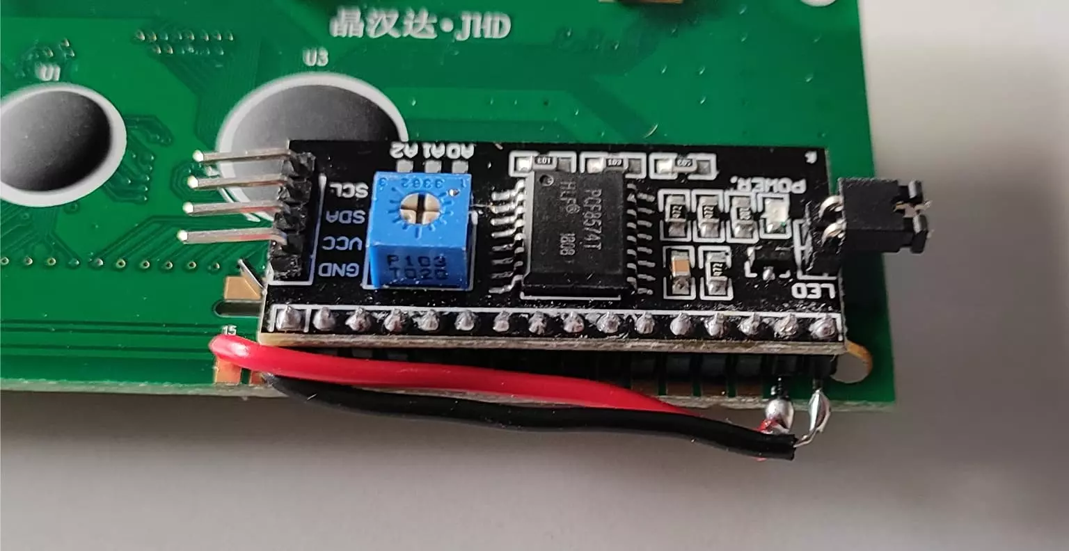
Finally, after all, connection and soldering work, the jumbo LCD should look like this.
Connect I2C Jumbo LCD to Arduino Board
As we have used the I2C extender board, the wiring between the LCD and Arduino board will be straightforward.
I2C extender board only provides 4 pins for controlling the display.
Therefore only 4 pins are needed for the I2C display instead of 12 pins in a regular LCD display.
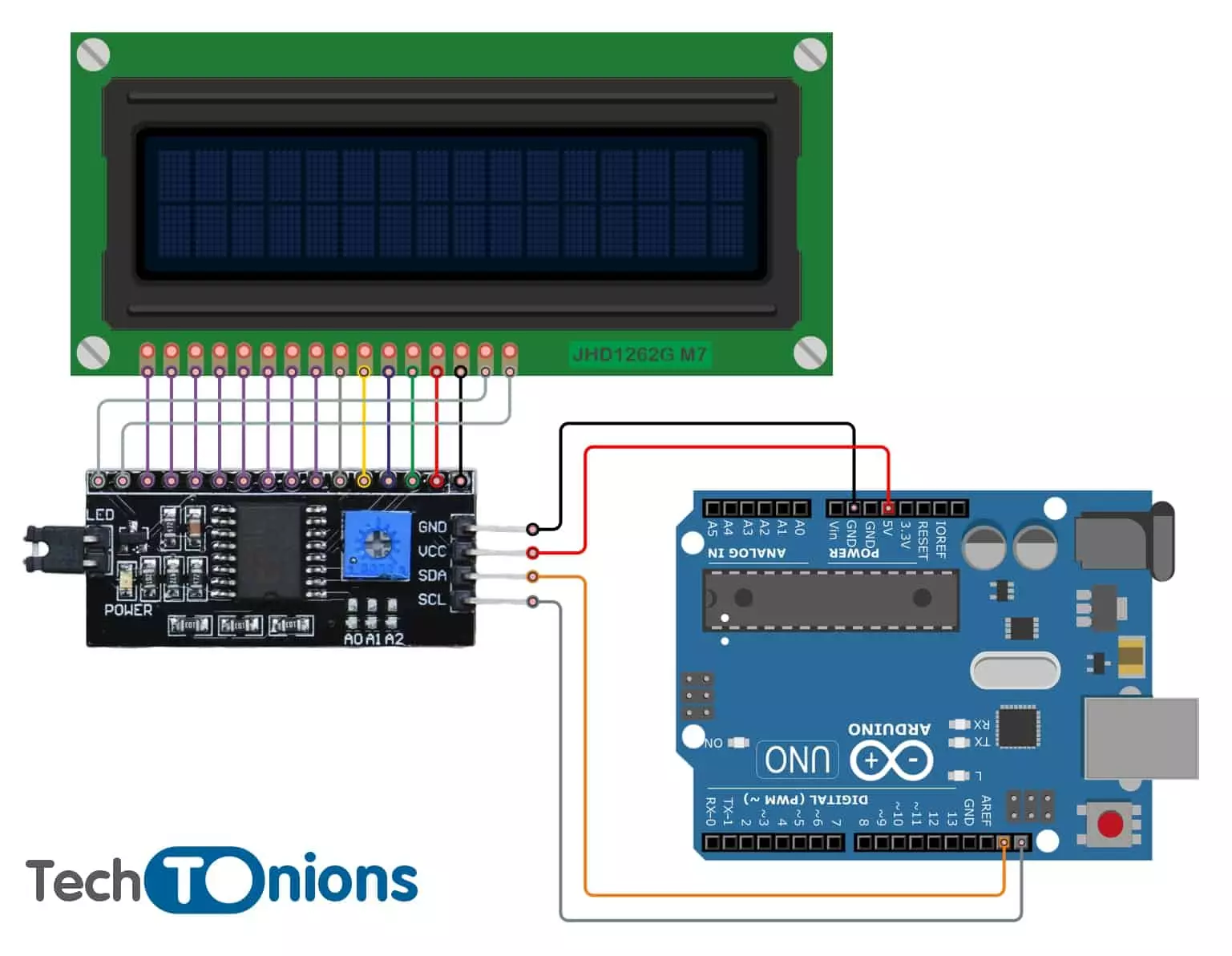
Start with connecting the VCC pin with the 5V of the Arduino board and the GND pin with the Arduino GND(ground) pin.
Only two pins are left for connection SDA and SCL; they are used for I2C communication.
We are using an Arduino UNO board for this tutorial, and in UNO SDA pin is at A4 and SCL at A5 pin. Additionally, both I2C pins in the Arduino UNO board are located above the Aref pin.
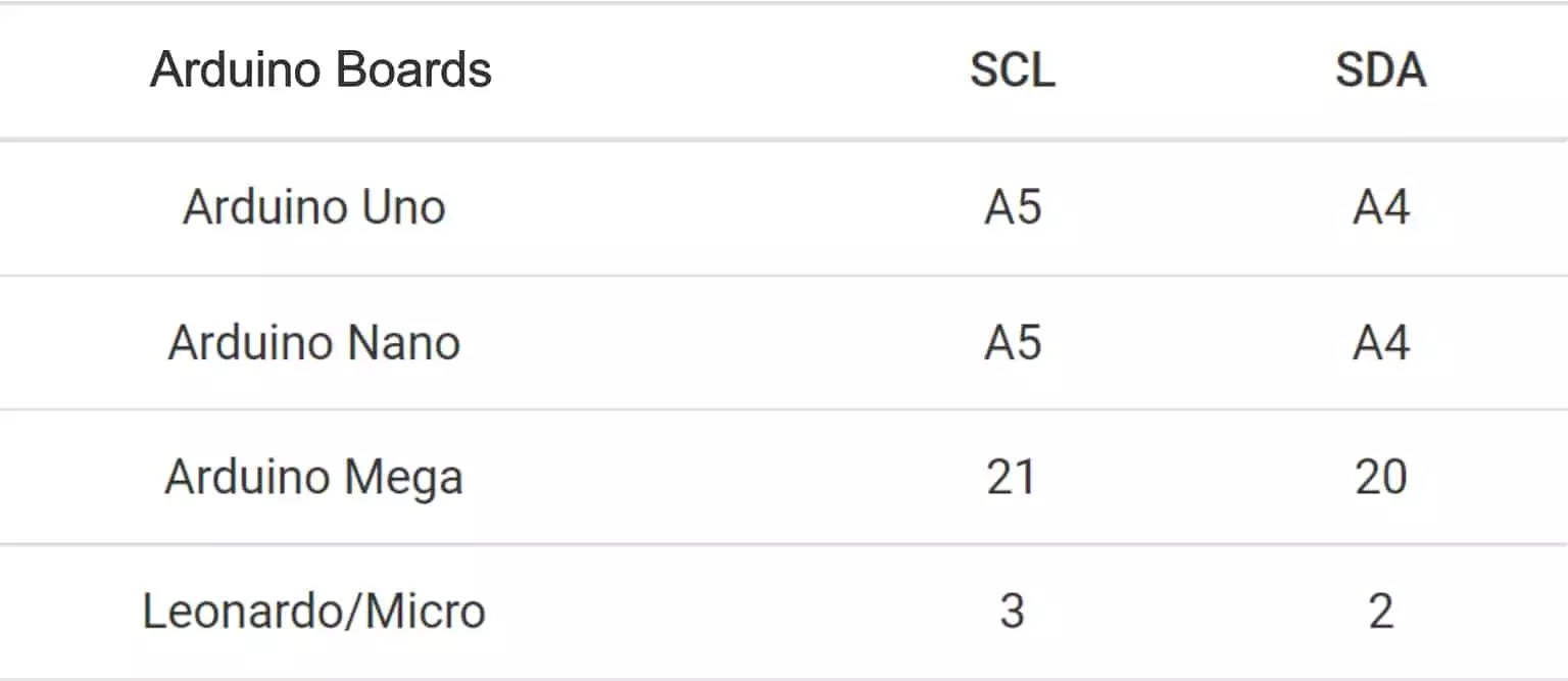
Note: I2C pins are different in different Arduino boards; therefore, refer to the table below if you are using other Arduino boards.
Requirement – Installing Arduino IDE
Before getting started with this tutorial, you will require Arduino IDE installed on your computer.
If you have already installed the latest Arduino IDE, then skip this step.
Else you can follow our easy-to-follow guide on:
❑ Getting Familiar With Arduino IDE
Installing I2C LCD Library In Arduino IDE
For effortless integration of I2C based LCD with Arduino, we will use a library known as LiquidCrystal_I2C.h. It is similar to LiquidCrystal.h in terms of usage. The main difference is that it can control display over I2C.
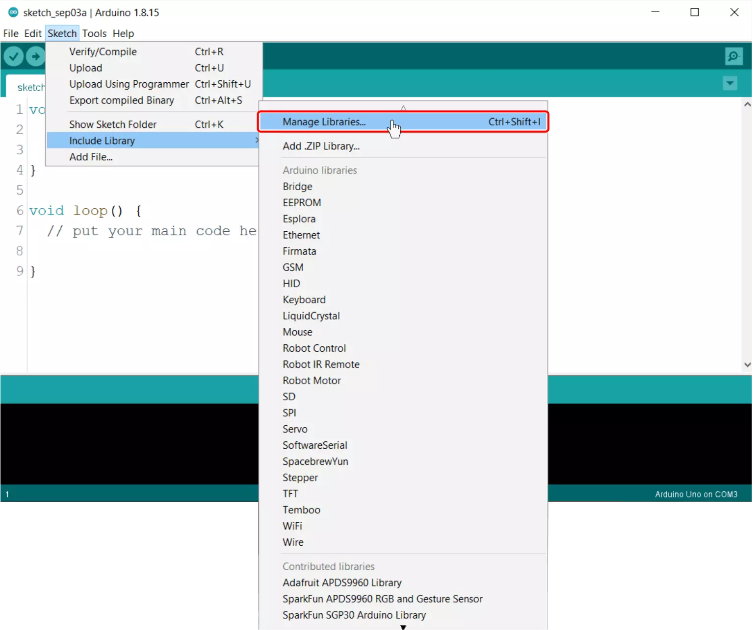
For installing this library, navigate to:
Sketch → Include Library → Manage Libraries
wait for a while until the library manager is opened, and it will download all the latest library indexes.
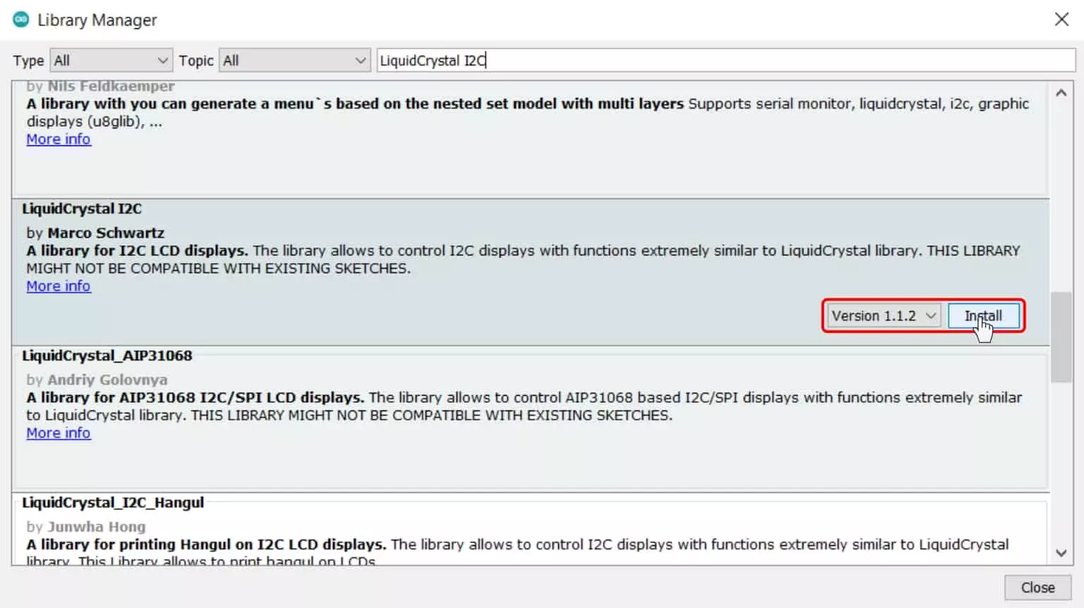
Now search for ‘LiquidCrystal_I2C’ in the search box. Look for a LiquidCrystal I2C by Marco Schwartz.
Select that and hit the install button.
If you want, you can also choose different library release versions.
For more information on the LiquidCrystal_I2C library, you can check out their GitHub repo.
Finding the I2C Address
Different I2C extenders will have separate I2C addresses as it depends on the manufacturer of the PCF8574 IC.
We can also modify the I2C address of the extender by a different combination with the SMD address jumper in the extender PCB.
It is only needed when you have more I2C devices in one bus and two clashing addresses.
To find the I2C address of LCD, we can run the I2C scanning code; it will contain two things:
- It will give us the address of the LCD
- And if we get the address, it means we have done the correct wiring.
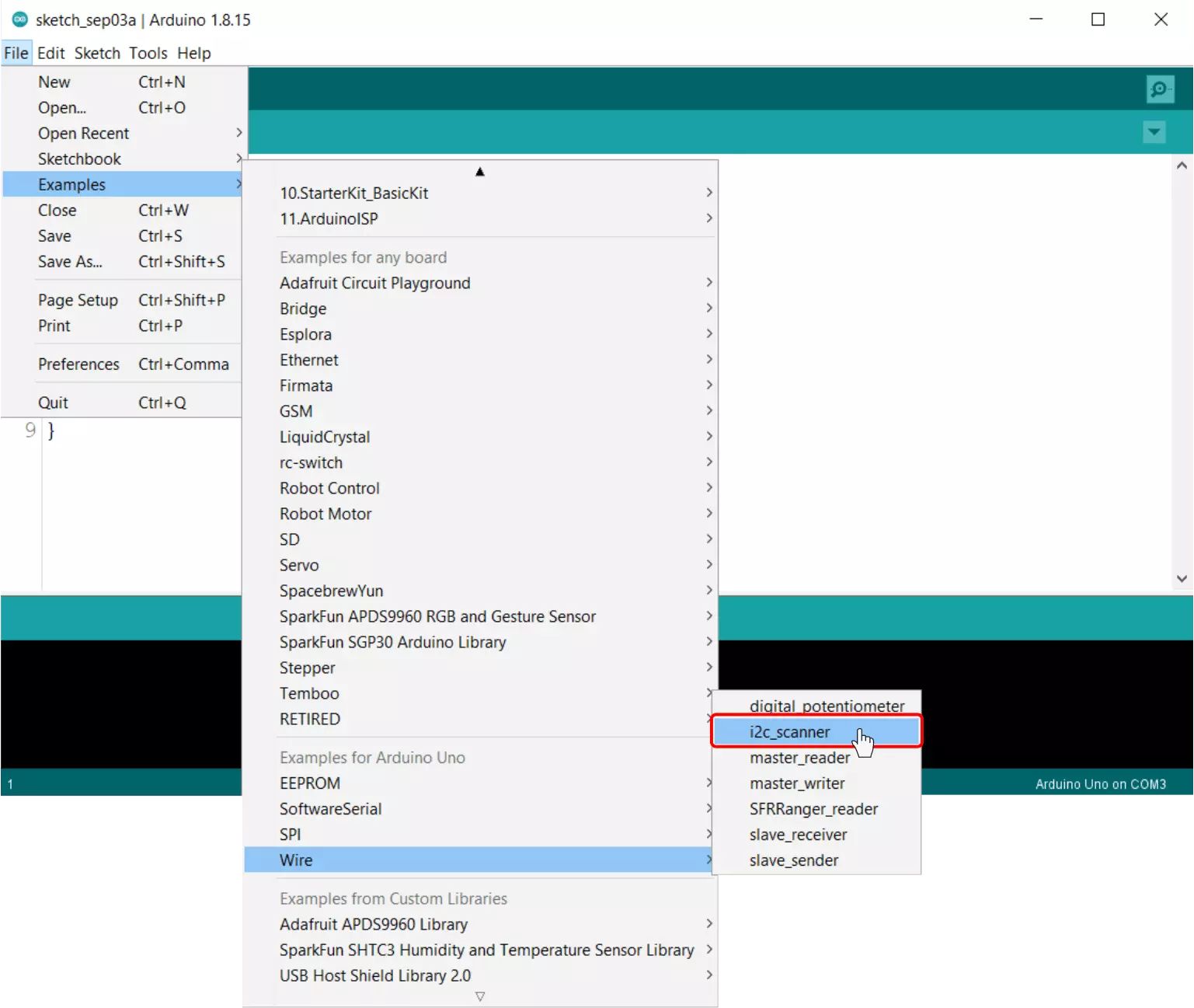
You need to upload this example present in Arduino IDE. Navigate to:
Files → Examples → Wire → i2c_scanner
Here is the complete code for the I2C scanner.
// --------------------------------------
// i2c_scanner
//
// Version 1
//    This program (or code that looks like it)
//    can be found in many places.
//    For example on the Arduino.cc forum.
//    The original author is not know.
// Version 2, Juni 2012, Using Arduino 1.0.1
//     Adapted to be as simple as possible by Arduino.cc user Krodal
// Version 3, Feb 26  2013
//    V3 by louarnold
// Version 4, March 3, 2013, Using Arduino 1.0.3
//    by Arduino.cc user Krodal.
//    Changes by louarnold removed.
//    Scanning addresses changed from 0...127 to 1...119,
//    according to the i2c scanner by Nick Gammon
//    https://www.gammon.com.au/forum/?id=10896
// Version 5, March 28, 2013
//    As version 4, but address scans now to 127.
//    A sensor seems to use address 120.
// Version 6, November 27, 2015.
//    Added waiting for the Leonardo serial communication.
//
//
// This sketch tests the standard 7-bit addresses
// Devices with higher bit address might not be seen properly.
//

#include <Wire.h>

void setup() {
  Wire.begin();

  Serial.begin(9600);
  while (!Serial); // Leonardo: wait for serial monitor
  Serial.println("\nI2C Scanner");
}

void loop() {
  int nDevices = 0;

  Serial.println("Scanning...");

  for (byte address = 1; address < 127; ++address) {
    // The i2c_scanner uses the return value of
    // the Write.endTransmisstion to see if
    // a device did acknowledge to the address.
    Wire.beginTransmission(address);
    byte error = Wire.endTransmission();

    if (error == 0) {
      Serial.print("I2C device found at address 0x");
      if (address < 16) {
        Serial.print("0");
      }
      Serial.print(address, HEX);
      Serial.println("  !");

      ++nDevices;
    } else if (error == 4) {
      Serial.print("Unknown error at address 0x");
      if (address < 16) {
        Serial.print("0");
      }
      Serial.println(address, HEX);
    }
  }
  if (nDevices == 0) {
    Serial.println("No I2C devices found\n");
  } else {
    Serial.println("done\n");
  }
  delay(5000); // Wait 5 seconds for next scan
}
After uploading this code, you only need to open the Arduino serial terminal.
If everything is correct, then you should see the address of your LCD. In our case, the address is 0x27.
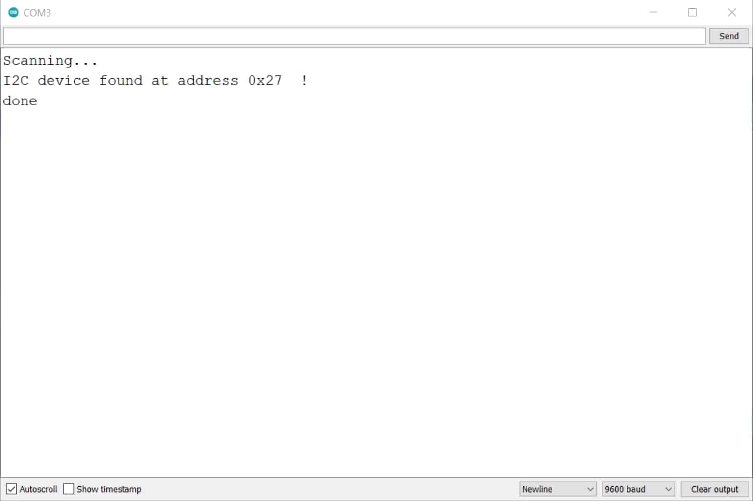
Please make a note of this address. You’ll need it in the following sketches.
Hello World In Jumbo LCD
Let us print our favorite Hello World! in our jumbo LCD.
We need to modify one line in this example code, where we will tell the code about our LCD address along with the max character and lines of our LCD.
In our case address is 0x27, the max character is 16, and the max line is 2; therefore, we will add this info as follow.
LiquidCrystal_I2C lcd(0x27,16,2); // set the LCD address to 0x27 for a 16 chars and 2 line display
Here is the complete sketch.
/*
  Date: 06-09-21
  Code written by: Tirth
  Printing Hello World In Lcd Display Example Code
  Find more on www.TechTOnions.com
*/

#include <LiquidCrystal_I2C.h>

LiquidCrystal_I2C lcd(0x27,16,2);  // set the LCD address to 0x3F for a 16 chars and 2 line display

void setup() {
  lcd.init();
  lcd.clear();
  lcd.backlight();      // Make sure backlight is on

  // Print a message on both lines of the LCD.
  lcd.setCursor(2,0);   //Set cursor to character 2 on line 0
  lcd.print("Hello world!");

  lcd.setCursor(0,1);   //Move cursor to character 2 on line 1
  lcd.print("Big LCD Tutorial");
}

void loop() {
}
After uploading this sketch to your Arduino board, you should see Hello World! written on your LCD like this.

Note: If you do not see anything written on your LCD, don’t worry; it may happen because you have not set the proper contrast of your LCD.
To do so, rotate the small trimport given on the I2C extender, and at some point, you will be able to see the text correctly in your LCD.
How It Works
The first step will be to include the required libraries. For handling LCD, we will use LiquidCrystal_I2C.h library.
#include <LiquidCrystal_I2C.h>
As discussed early, we need to tell the library about our LCD address and LCD size. Additionally, we will create lcd as an object.
LiquidCrystal_I2C lcd(0x27,16,2); // set the LCD address to 0x3F for a 16 chars and 2 line display
setup()
First thing inside the void setup, we will initialize the LCD object using the init() function.
lcd.init();
We will clear the LCD by using the clear() function to ensure that our LCD starts clean every time.
lcd.clear();
And we are turning on the backlight with the backlight() function.
lcd.backlight(); // Make sure backlight is on
The home position of the LCD cursor is at the top left corner colom=0 and row =0. We can set the LCD cursor to the new location by using the setCursor() function.
Let set the cursor location to character 2 and line 0.
lcd.setCursor(2,0); //Set cursor to character 2 on line 0
Next, we will print Hello World! string by using the print() function. This function is similar to the serial print function, but it prints the string in LCD instead of the serial monitor.
lcd.print("Hello world!");
Similarly, we will print Big LCD Tutorial on the second line of the LCD by using the following sequence of codes.
lcd.setCursor(0,1);   //Move cursor to character 2 on line 1
lcd.print("Big LCD Tutorial");
Apart from this example, you can use different functions from this library to control this big LCD similar to your small one.
Wrapping Up
We have seen how easy it is to integrate a bigger LCD in your Arduino-based project. As the programming structure of the big LCD is the same, we can use our existing code for the new display.
If you like our tutorial, then consider subscribing to our weekly newsletter.
Also, share your thoughts and your LCD project in the comment section.


Its a simple to understand tutorial very informative
Thank you, Pranav Patil.