We should be thankful to Donald Macadie, the inventor of the first multimeter.
Every maker should know how to use a multimeter as it’s an essential step toward learning electronics. We’ll explore all the standard features of a digital multimeter (DMM) in this guide.
You will learn the following things about multimeters:
- Multimeter use
- Different parts of the Multimeter
- Selecting a right Multimeter
- Multimeter Symbols
- Measuring Voltage
- Current Measurement
- Measuring Resistance
- Continuity Testing
- Diode Testing
- Transistor Testing
- Changing Fuse/ Battery
1. Multimeter use
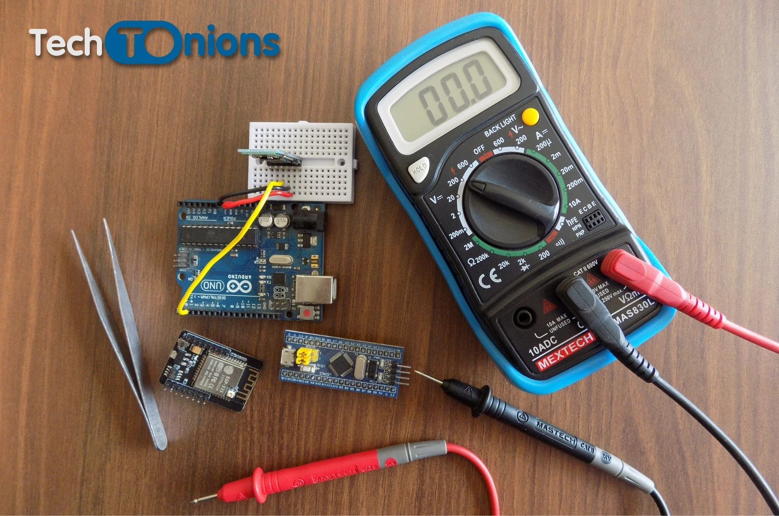
A doctor can not hear heartbeats without a Stethoscope. Similarly, a maker needs a multimeter to debug the electronic circuit. As we can not see how electricity is flowing in our circuit with our eyes.
Here are a few movements when your first choice of weapon will be a multimeter while building an electronics project.
- Why my circuit is not working?
- How much juice does my battery have?
- Do all connections are proper?
- The jumper wire is broken or not?
And many similar movements that you will find as it’s all part of the learning curve. Just connect your multimeter probes to the circuit and be a part of your circuit.
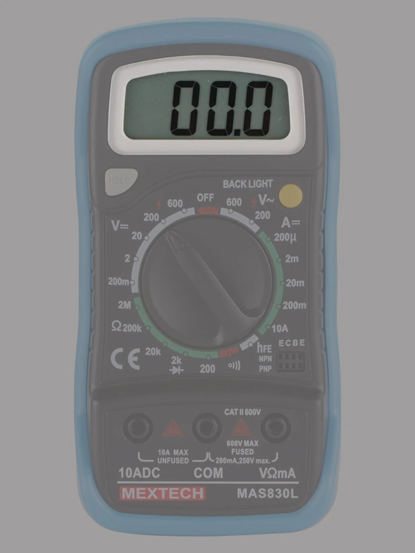
2. Different Parts Of Multimeter
Pretty much all multimeter has four main part categorized as:
1. Display
All Digital multimeters will have a display to display the measured values. Display size, shape, and types vary between different multimeters. Mostly all DMM will have at least four digits display.
Additionally, it will have a few symbals for displaying various functions such as a negative sign, Knob selection symbol, hold symbol, and many more.
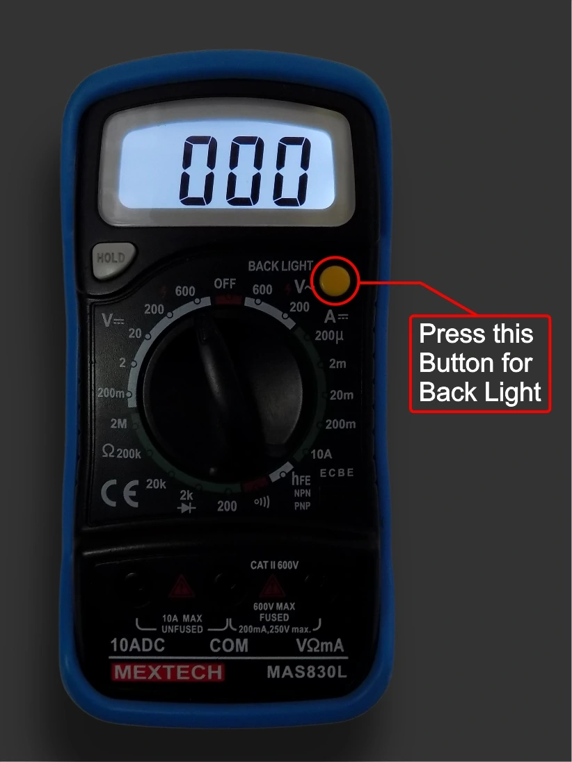
Generally, DMM will have a button to illuminate the backlight in the display for better visibility in a dark environment.
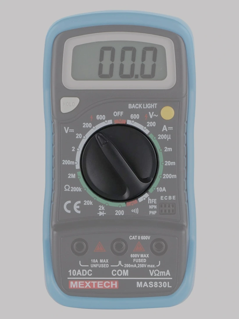
2. Selection Knob
All multimeters will have a Selection knob in the center portion. The selection knob allows the user to switch between different measurement options that the multimeter allows.
Such as voltage measurement, current measurement, resistance measurement, etc.
3. Ports:
Every multimeter will have at least three ports on the bottom part.
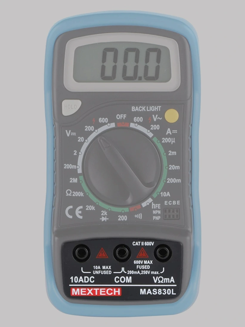
There will be a COM port that stands for common, and it will always be connected to Ground or ‘-‘ in any DC circuit as AC will not have any polarity.
Note:- Always connect the Black probe to the COM port.
Another port will be mAVΩ used for measuring voltage, Current in Milliampere range, Resistance, Diode plus continuity testing, and more. Additionally, this port will have an internal fuse as per the maximum current rating for protection.
Another special port is 10A. Used to measure the only current in the Ampere range >200mA. Additionally, this port will have an internal fuse as per the maximum current rating for protection.
4. Probes:
Every multimeter comes with at least two probes one will be black, and another will be red color.
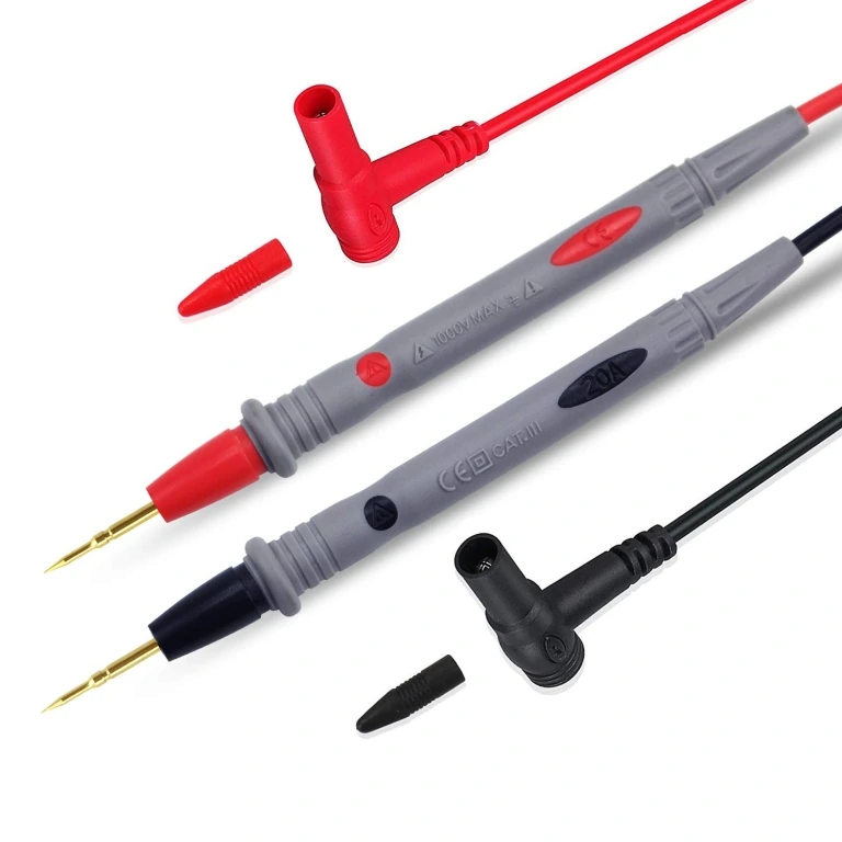
Note:- It’s just a color difference rest of both probes have identical properties. Black stands for negative and red stands for positive as a standard.
Your multimeter will have different probes if it has additional features like temperature measurement.
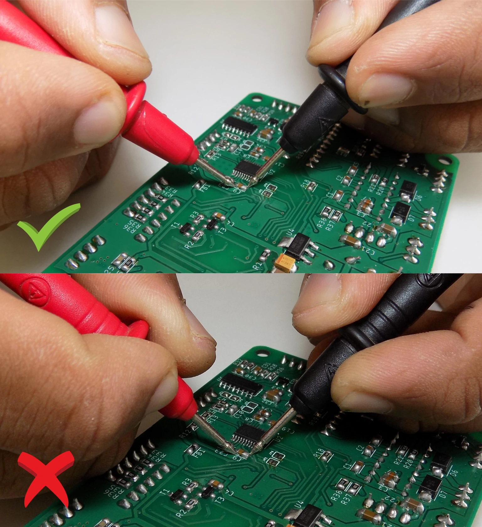
The standard probe will have a guard ring on them. It prevents your hand to slip into the live measuring circuit accidentally. Therefore always hold your probe above that guard ring as it is the industrial practice for your safety.
3. Selecting Right Multimeter:
The selection of a good Multimeter is essential for your usage as well as your safety.
Buying the Proper multimeter depends on your requirement. Many DMM will have additional features such as Capacitance, Temperature or frequency measurement, etc.
It might happen that you need that additional feature in your multimeter to suit your needs.
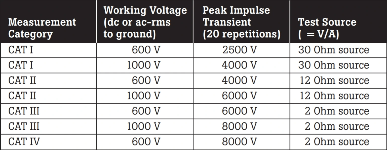
Besides, all digital multimeters have different category classes such as CAT I, CAT II, CAT III, and CAT IV. All Categories have different usage requirements specified in the given table.
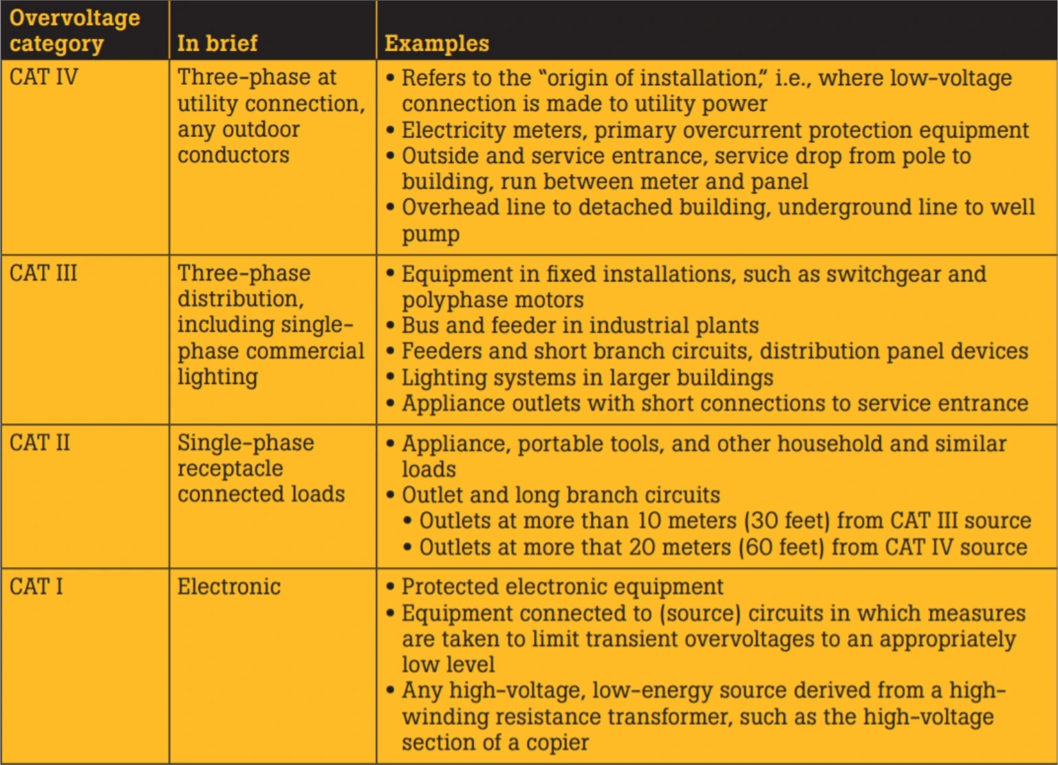
So, if you are a maker or an electronics hobbyist like us, then CAT I will be more than you require. Also, different levels of protection are provided based on measuring voltage for each category shown in the table.
Therefore CAT I multimeter has sufficient protection provided to measure voltage up to 600v. Also, for your protection, different peak transient voltage protections are provided. You can check more on the Fluke Multimeter safety guide here.
Apart from this, we recommend you buy multimeters that have
- Protective hard rubber cover as many times as you will drop your DMM.
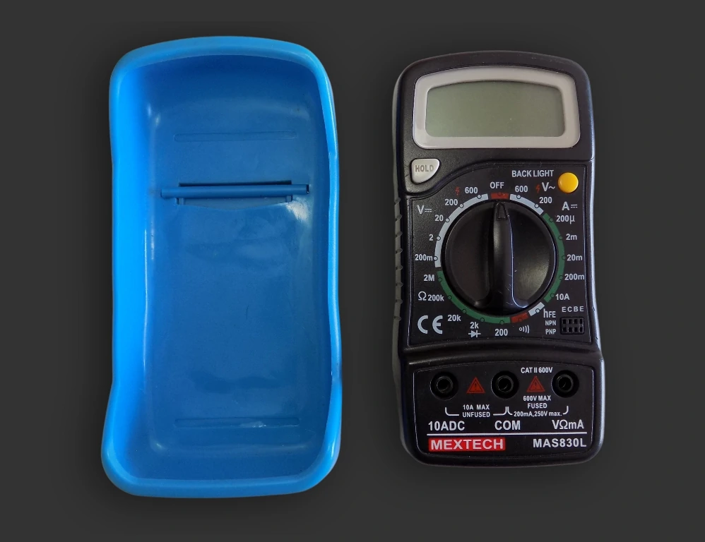
- The cover should have a stand so that you can hold both probes at a time without holding a multimeter.
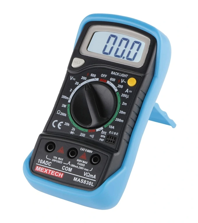
- It should have a backlight if you work with DMM in an outdoor environment.
4. Multimeter Symbols
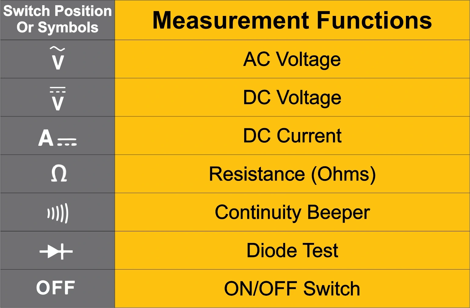
From voltage and resistance measurements to testing continuity and diodes, each symbol on the multimeter represents a unique capability.
There are different symbols given on the multimeter selection knob. Each represents different meanings. Common Symbols are DC voltage, AC voltage, DC current, Resistance, Diode, continuity, etc.
Additionally, for a better understanding of proper multimeter knob selection, you can press different buttons given below to see which area you can set your multimeter knob.

5. Measuring Voltage:
Let's measure the voltage of an AAA battery. Now plug the black probe into the COM port and the red probe into mAVΩ.
We want to measure the battery, and all batteries and portable electronics work on direct current (DC). Therefore our selection knob will be set to a V with a straight like on as it represents DC voltage.
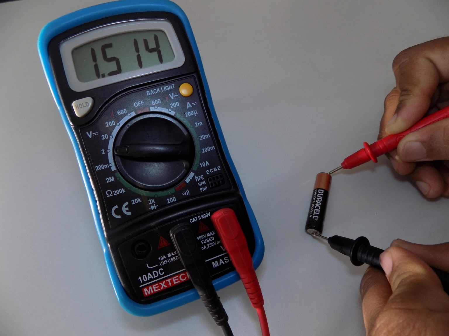
Now we know that the AAA battery voltage will be around 1.5v. So set the knob to 2v DC.
Now gently place red prob to '+' of battery and black prob to '-' of battery and apply gentle pressure for better contact between the battery terminal and prob needle.
You will see the battery voltage of around 1.5v on the multimeter display.
Note:- Always remember voltage measurement is done in parallel, not in series.
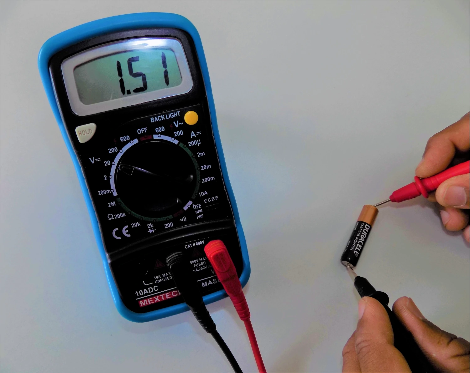
What if we set the knob to 20v instead of 2v?
The multimeter will still show the readings, but it will be less accurate than the 2v range.
So for good measurement accuracy, you must select the proper range.
What if you swap the red and black probes? What if you don't know the polarity of battery terminals?
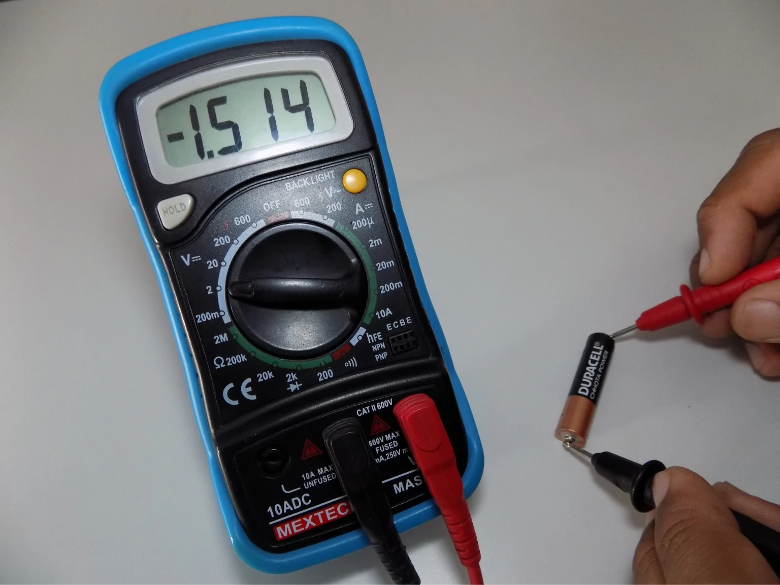
Don't worry, nothing wrong will happen. The multimeter will only display the negative value in the display.
It is the best method to know the correct polarities of any battery or power pins in a circuit.
Why my multimeter is showing 1 or -1 on display?
The DMM display will show you 1 or -1 in overload conditions (when the measured value is greater than the range you have selected. Therefore increase the selection range by one step and more if it again shows 1.

Note:- Some multimeters have auto-range functionality so that you do not have to worry about proper range selection. You can check out Fluke177 Multimeter.
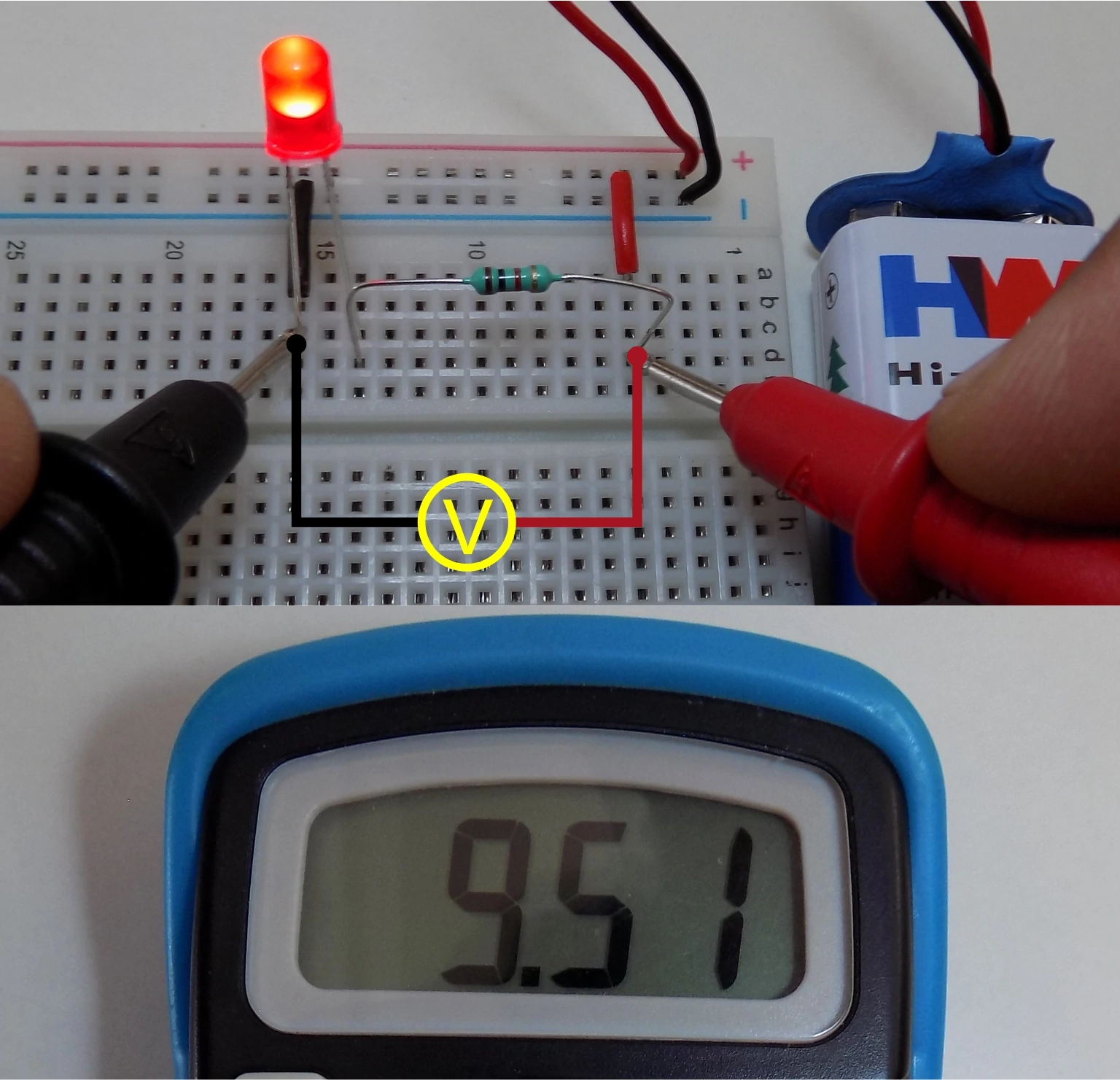
To measure the voltage across any component, you have just to put two probes across its terminals. Taking an example of a simple LED glowing circuit let's measure the Voltage drop across the different components. As a result, the LED voltage drop is around 2V.
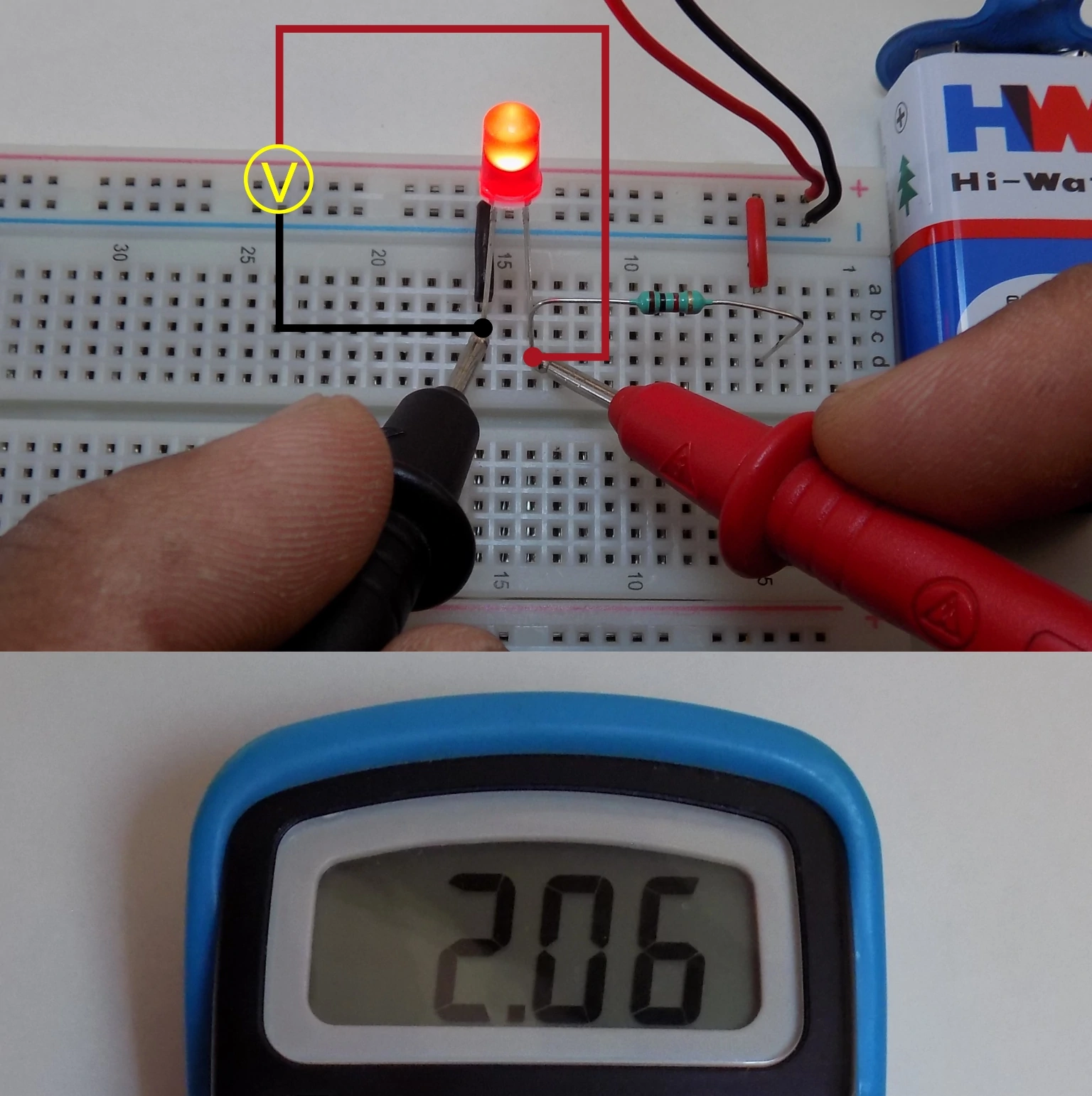
Let's measure the voltage drop across the 1K resistor used in the circuit. Which is around 7.46V as shown in the multimeter display.

You can measure the individual voltage drop of any component in the circuit using a multimeter. And the total drop of every component will be equal to the source voltage. Therefore in our example source voltage is 9.51V (new 9V battery) which is equivalent to 2.06V + 7.46V.
⚠ In many modules, VCC and GND pin as near to each other. Therefore make sure you do not touch red and black probes to each other while voltage measurement. It will short the VCC and GND of the circuit, and it can blow out.
To measure Alternating Current (AC) voltage, you have to set the knob to V with a wave symbol representing AC voltages. Now you have to select an appropriate range for your measurement.
AC voltage doesn't have polarity; therefore, connect any probe to any terminal. For this example, we are measuring AC voltage going to 12V SMPS. At present the value of grid AC voltage was around 256V (230V & 110V are standard grid voltage).
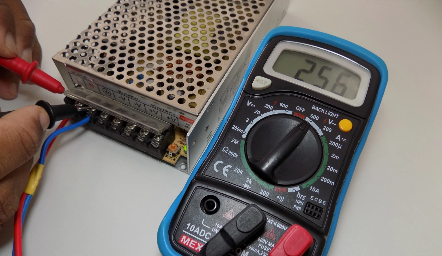
⚠ Always take proper precautions before measuring high AC voltage.
6. Measuring Current:
Measuring current using a multimeter is a little bit tricky as the current needs to be measured in series.
Therefore to measure the current in any circuit loop, you need to connect the multimeter in series in that particular current loop you want to measure.
Therefore to do so, you need to break your existing circuit to add multimeter probes in series.
The multimeter will act as a wire in your circuit, and it will measure the current passing through its wire.
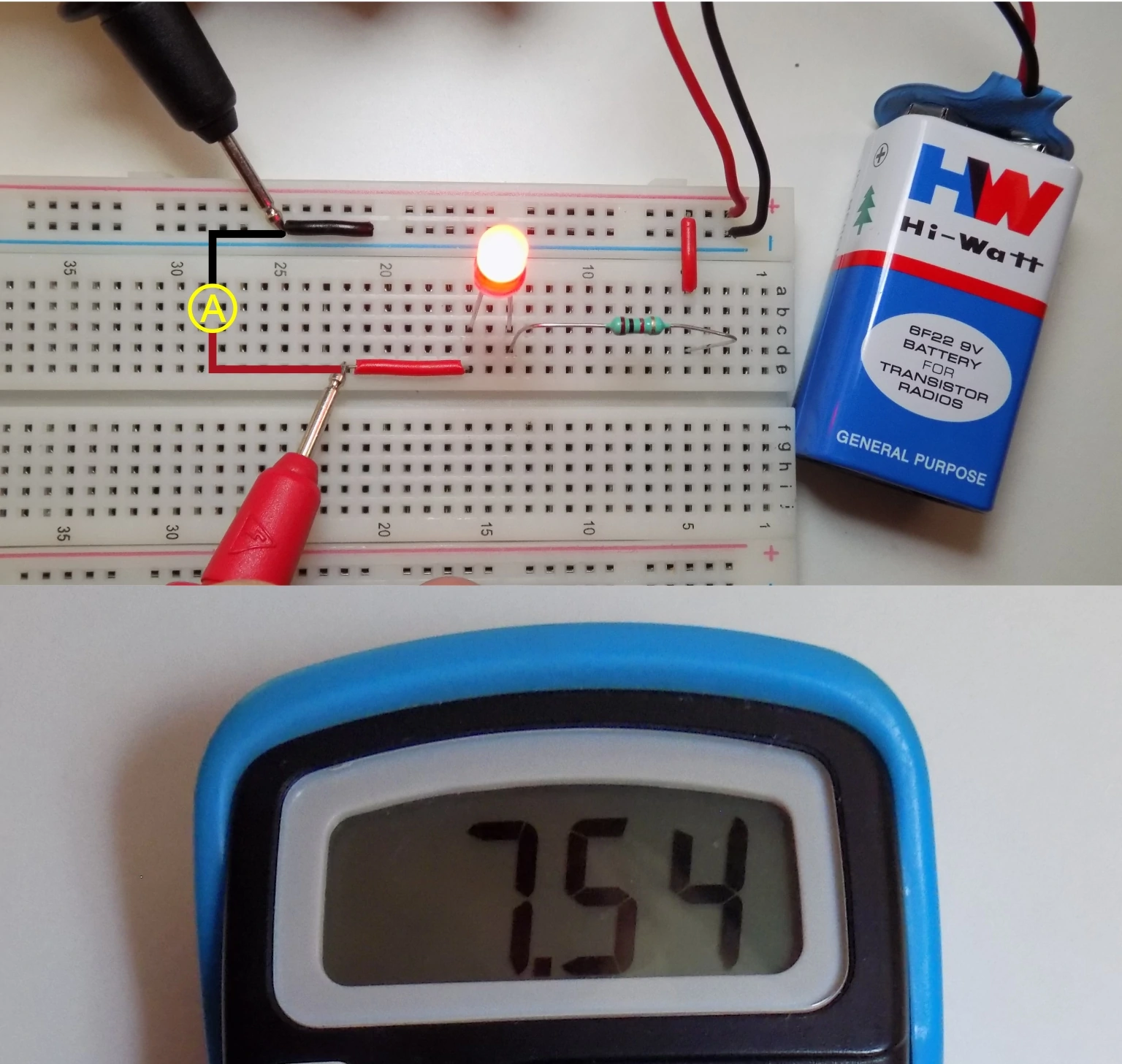
As you see in we are measuring current in an elementary LED circuit hooked up with a 1K resistor and 9V battery. Therefore set the selection knob to the 20mA range.
Remember, you can measure current up to 200mA in DC by using the mAVΩ port. If you want to read a current of more than 200mA, you have to insert a red probe into the 10A port. And the selection knob is also at 10A.
⚠ Be careful while measuring high current as it can be lethal.
More advanced Multimeters like Fluke177 also can measure current in AC circuits.
Suppose you need to measure high current daily. In that case, we suggest using a clamp-on meter to measure current as it is safer than a regular multimeter.
Current measuring is essential when you are designing a low-power project. As it depends on current consumption that how long will your battery will provide power.
⚠ After measuring, don't forget to switch it off as most of us have a terrible habit of directly measuring voltage with a multimeter without looking at the knob setting. And if you measure voltage with a knob setting on current, you are shorting VCC and GND of the measuring circuit. It will blow up your multimeter's internal fuse. Additionally, turning it OFF will save the battery.
7. Measure Resistance:
Measuring the resistance of a resistor using a multimeter is very simple.
Resistors don't have polarity, so no need to worry about that.
Generally, all through-hole resistors will have color codes, and SMD resistors will have value code on them. Still, measuring resistance can be a handy feature.
Let's measure a 1K resistor value with a multimeter.
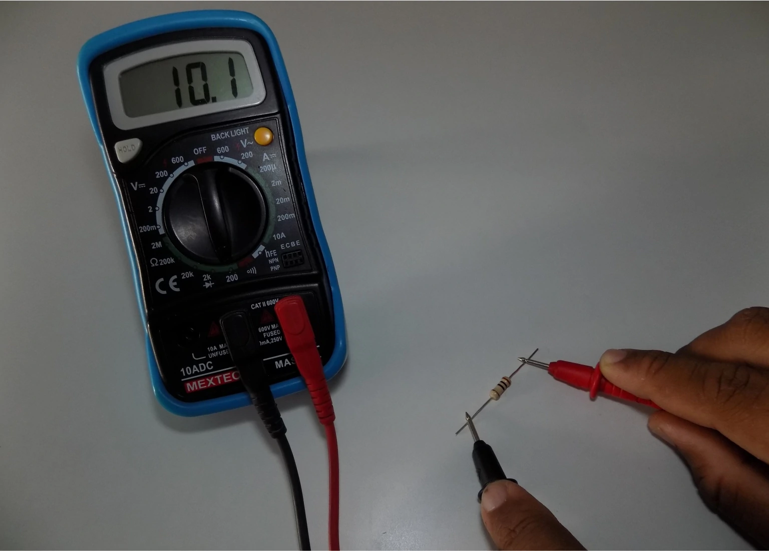
We know the value of the resistor; therefore, will set the knob to 2K in the Ω region. If you don't know the value of the resistor, start with the center, which is 20k, and start measuring.
Now you have to just gently press the red and black probes across the resistor leads. And the multimeter display will show the value.
If you have selected the 20K and the displayed value is less than 2, you can use the 2K range for better accuracy. If it shows 1 or OL(overload), go to the next more significant value, which is 200k.
Repeat the same process until you get the preferred range for the measurement.
Note:- Different resistors have different accuracy, and most of them are 5% accurate. It means that the actual value of a 1K resistor can have a ±5% variation. Therefore measured value will be near 1K, not the exact 1K.
8. Testing Continuity:
Testing continuity is the same as resistance measurement. Just place both multimeter probes at any two points in your measuring circuit.
Suppose there is low resistance like a few Ω's. In that case, a multimeter will make a beep sound and display a value near 0, hence ensuring the proper conductive path between the two measures point.
If the value of resistance is high, no beep sound and the display value will be 1 if two points are entirely isolated. It will show the high resistance value between the two points.
Continuity testing is most required to detect that the connection between two points in the circuit is proper. This test also helps us to detect two points that are connected that should not. Set the selection knob to a speaker-like symbol to perform a continuity test.
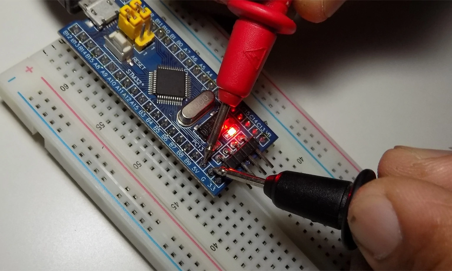
As you can see, we are testing continuity in a PCB track. The first test detects the electrical connection. We hear a beep sound, and the display shows 0.
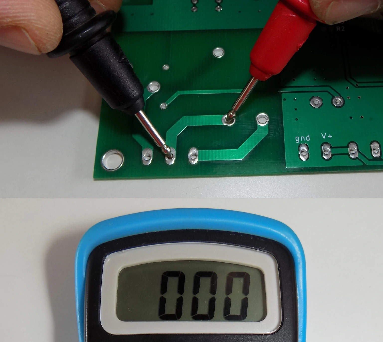
There is no electrical connection in the second test. Therefore, no beep sound, and the display shows 1.

Another handy trick with continuity test, is you can test whether LED is working or not. Additionally, you can find the polarity of the LED using this method.

9. Diode Testing:
Diode testing is similar to the continuity test, but the meter does not emit a beep sound in this test.
Set the selection knob to the diode symbol and place the probes across the diode.
A good Forward based diode will display the voltage drop of the diode between 0.5 to 0.8 volts. Therefore, our diode is in good condition.
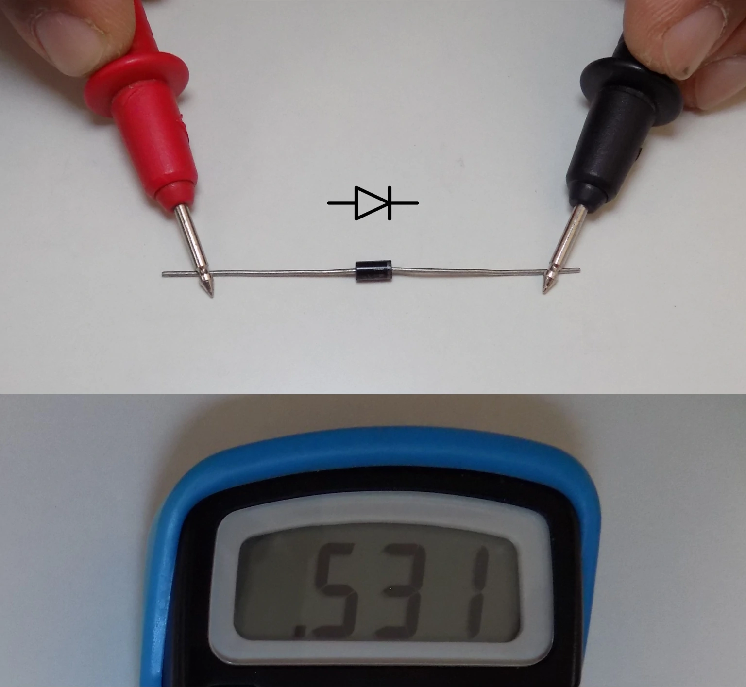
Note:- Some germanium-based diodes also have low voltage drops between 0.2 to 0.3 volts.
A bad diode(open) will not allow current to flow from any direction so the meter will display 1 or OL.
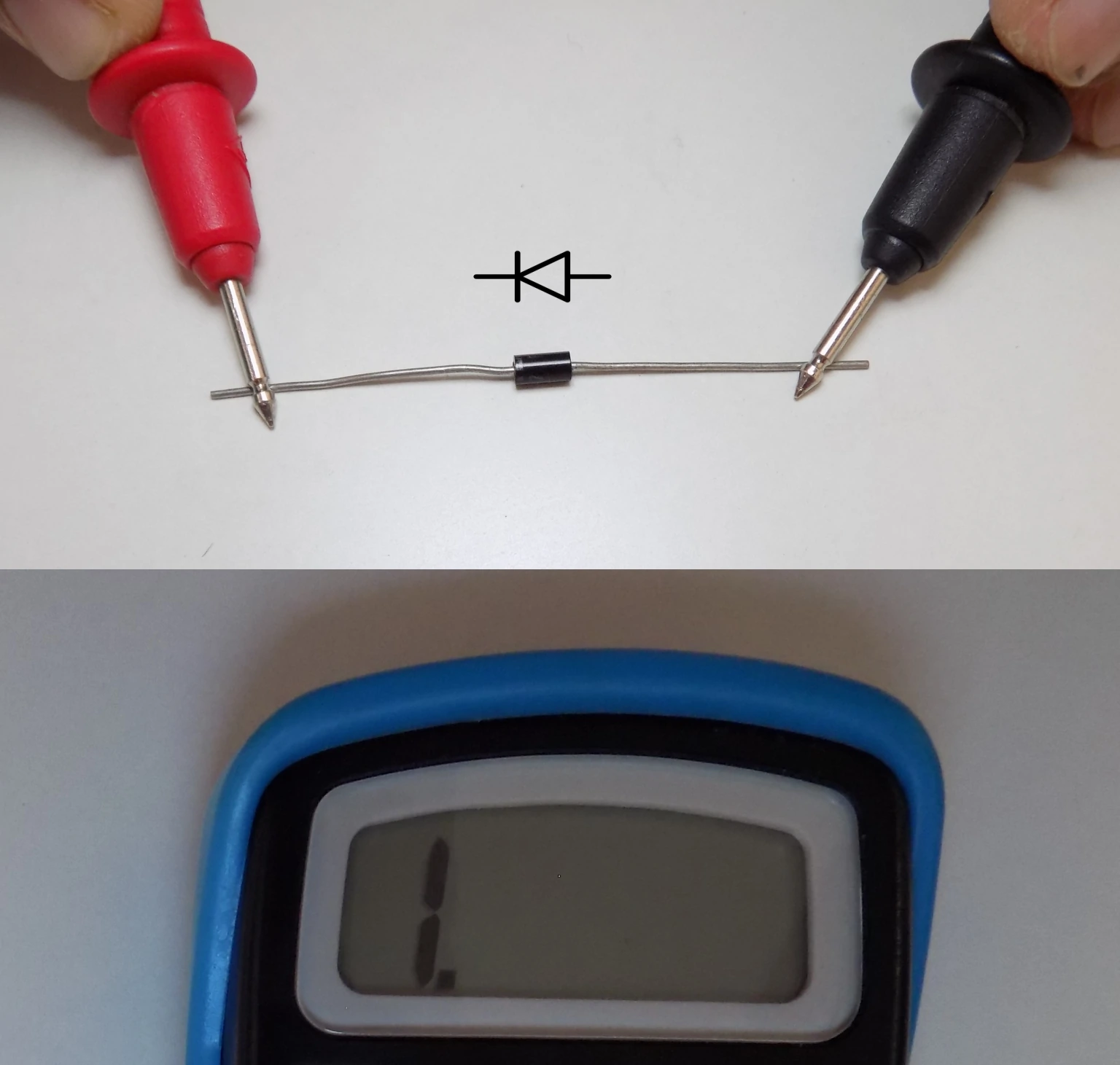
And if the diode is shorted, it will allow the current to flow in both directions and get a proper voltage drop reading in both directions.
10. Transistor Testing:
Few low-end multimeters have the functionality to test transistors. They have the Hfe symbol on the selection knob, which represents the transistor's DC current gain. By performing this test, you can also identify the correct pins of the transistor.
For this example, we will use well known BC547 NPN transistor, which has an Hfe between 110 to 800. If you know the pinout of your transistor, then insert it according to the slots given near the Hfe selection.
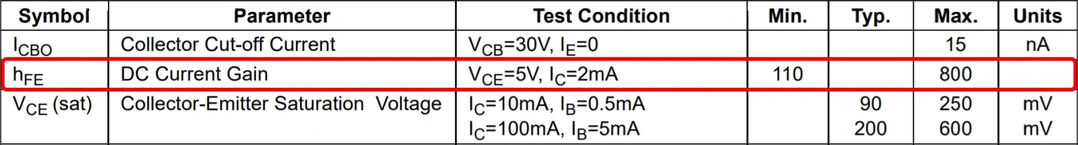
If a transistor is in good condition meter will show its DC current gain value between 110 to 800 as per the datasheet.

As a result, we get the value of 364 which means the transistor is in working condition.
Now let's try inserting the transistor in the wrong way.
The meter will show 0 in the display as the pinout of the transistor does not match. You can test both PNP and NPN transistors.
11. Changing Fuse or Battery:
If your multimeter battery is dead or you have accidentally blown the internal fuse while learning. Don't worry; we are sure every one of us has blown the multimeter fuse once.
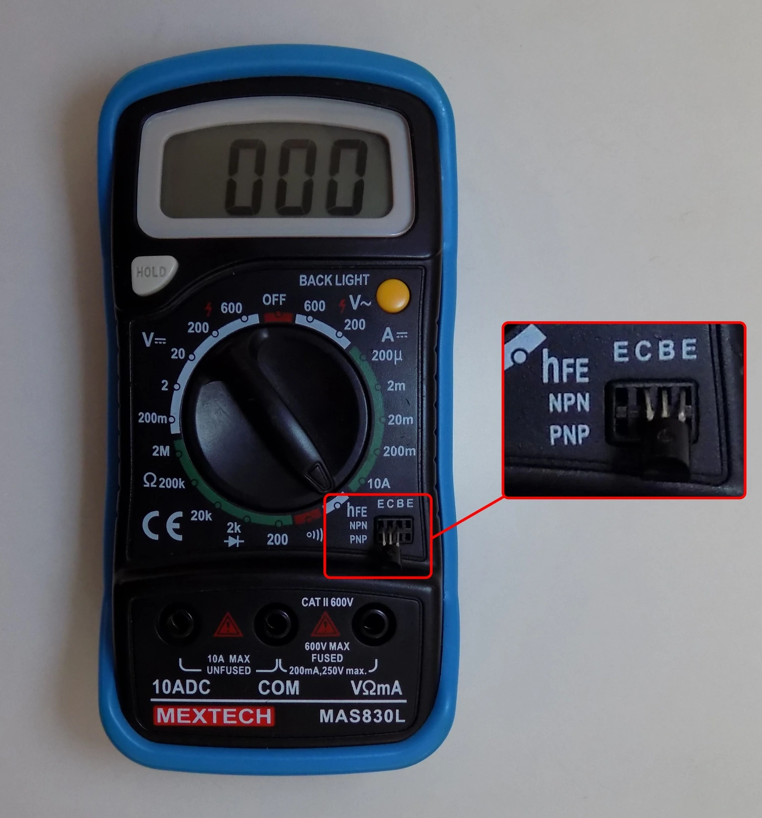
Time to change it. You need to open the back cover of your multimeter. It will require a few screws to remove first to open the back cover. And there you will see two fuses in the multimeter PCB. Identify the burned fuse and replace that fuse with the same value.
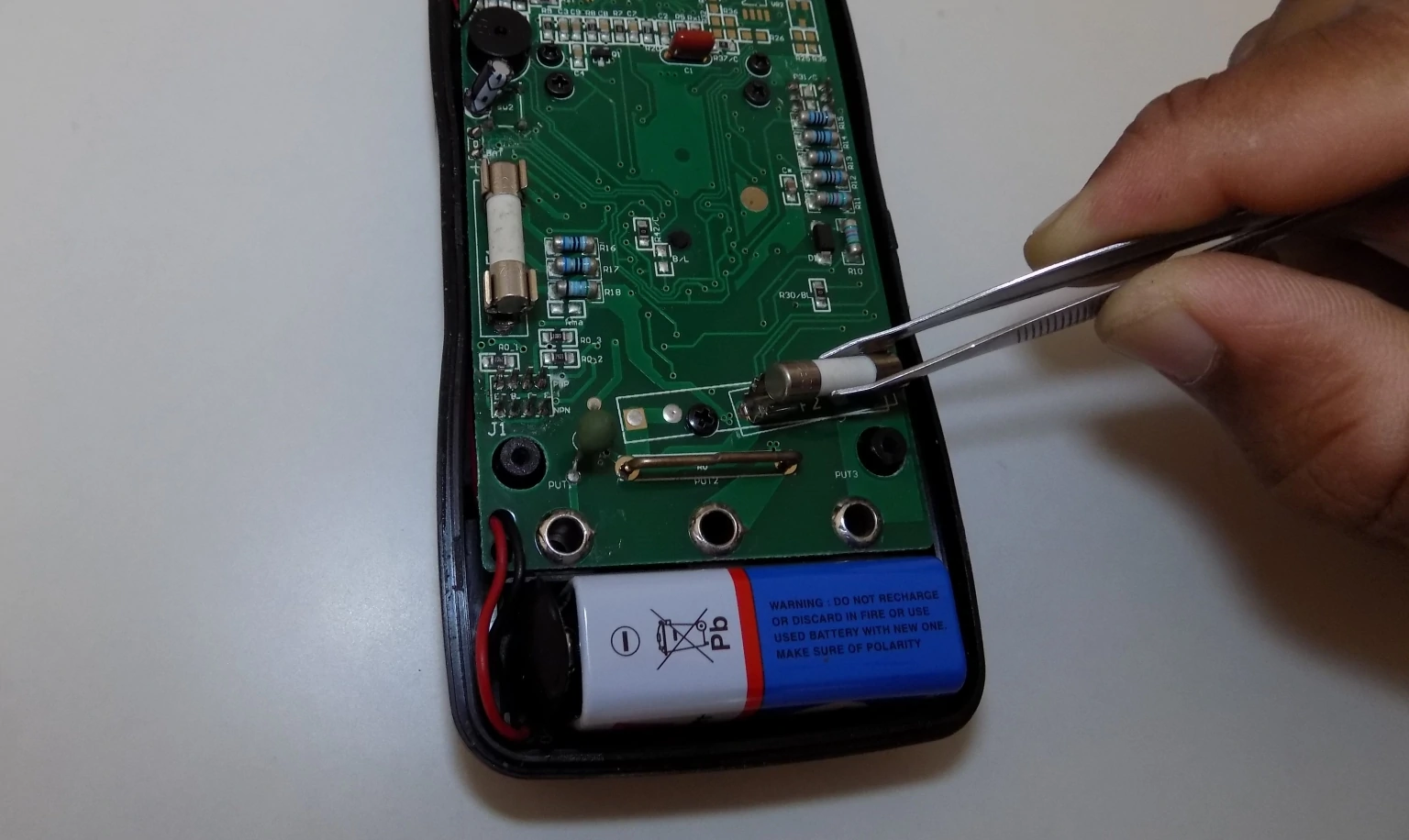
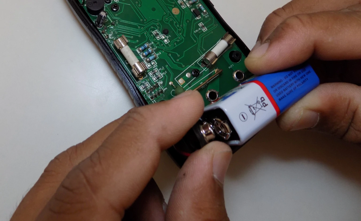
Below PCB we can see the 9 Volt battery and we will replace it with a similar battery.
Conclusion
We hope you all now know how to use a multimeter and it will help to enhance the level of your electronics projects by one step. Do share your story/experience of using your first multimeter in the comment section below.
And if you enjoy reading our content then consider subscribing to our weekly newsletter for more updates.


This is one of the best introductions to multimeters I have come across. Great tutorial!
Superb explanation and amazing photos guys 👍 👍 🔥
Really…… Helpfully thanks alot……….
Thank you, Robin great to know that you our guide was helpful to u.
Thanks for sharing this valuable information.
Thank You.😇