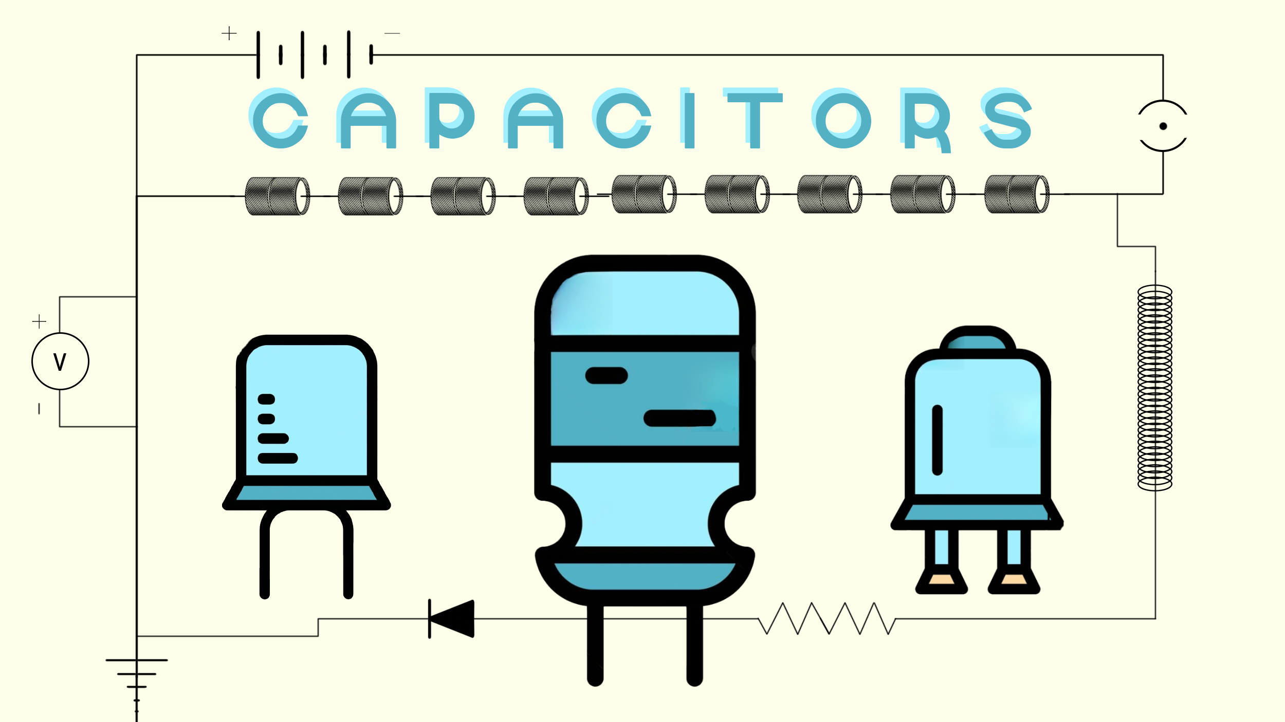
In the world of electronics, capacitors are fundamental components that play a crucial role in storing and releasing electrical energy. Whether you’re an electronics enthusiast or just curious about how devices work, understanding capacitors is essential.
What is a Capacitor?
A capacitor, in its simplest form, is an electronic component designed to store and release electrical energy. Think of it as a tiny, rechargeable battery that can store and discharge energy almost instantly. Unlike batteries, capacitors don’t produce energy; they store it for later use.
Capacitor Symbol and Diagram
Before we dive deeper, let’s familiarize ourselves with the symbol and diagram used to represent capacitors in circuit schematics. Understanding these symbols will be essential as we explore various circuit configurations later in the article.
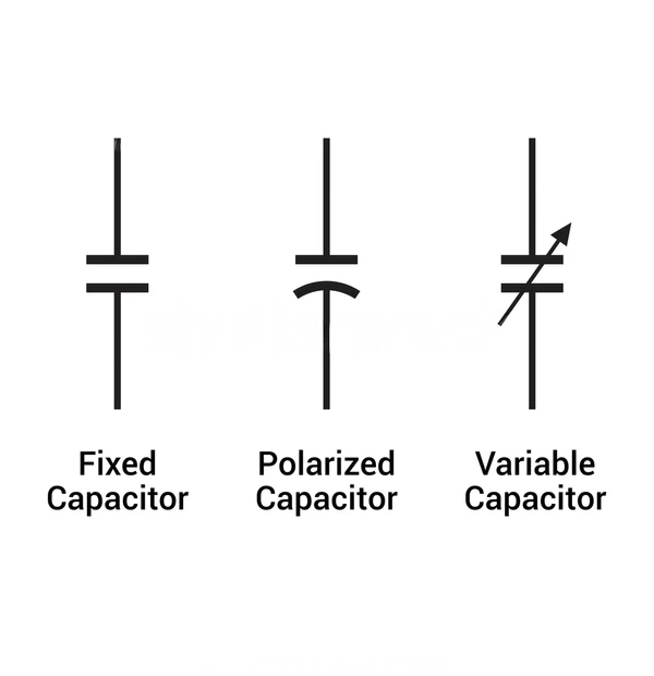
The standard symbol for a capacitor consists of two parallel lines representing the plates, with a curved line connecting them, symbolizing the dielectric.
Capacitance of Capacitor
It’s the measure of a capacitor’s ability to store electrical energy when voltage charges it up. It supports voltage smoothing, noise filtering, and device stability. With capacitance values spanning microfarads to farads, it serves as an electrical reservoir, ready to deliver stored energy when circuits require assistance.
This property influences how effectively a capacitor can smooth out voltage fluctuations, filter unwanted noise, and contribute to the stability of electronic devices.
So, the next time you power up your gadgets, remember that capacitance is there, providing that reassuring electrical hug, ensuring everything runs smoothly.
Capacitor Formulas
Let’s start with the most fundamental concept: capacitance. Capacitance (C) measures a capacitor’s ability to store electrical charge. It’s like the size of a magical bag that can hold more or fewer electrons. The formula for capacitance is:
- C: Capacitance in Farads (F)
- Q: Electric charge in Coulombs (C)
- V: Voltage across the capacitor in Volts (V)
In simpler terms, capacitance tells us how much charge (in Coulombs) a capacitor can store for every Volt of voltage applied.
Energy Stored (U) Formula
Now, let’s explore the energy stored in a capacitor, a concept akin to a wizard’s spellbook filled with magical energy. The energy stored (U) in a capacitor is given by:
- U: Energy stored in Joules (J)
- C: Capacitance in Farads (F)
- V: Voltage across the capacitor in Volts (V)
This formula tells us how much energy a capacitor can hold, and it’s directly proportional to the square of the voltage applied.
Time Constant (τ) Formula
Next, let’s introduce the time constant (τ), which describes how quickly a capacitor charges or discharges. It’s like a wizard’s wand movement, determining the pace of magic. The time constant formula is:
- τ: Time constant in seconds (s)
- R: Resistance in Ohms (Ω)
- C: Capacitance in Farads (F)
This formula tells us how long it takes for a capacitor to charge or discharge through a resistor. A smaller time constant means faster changes.
Series and Parallel Capacitors
In electronics, capacitors are often connected in various configurations to achieve specific electrical characteristics. One of these configurations is connecting capacitors in series. When capacitors are arranged in series, their overall capacitance changes, and understanding the series formula is essential for designing circuits and predicting their behavior.
Parallel Capacitor
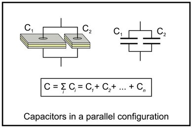
In a parallel configuration, capacitors are placed side by side, forming multiple paths for the flow of electrical current.
Parallel capacitors each experience the same voltage, but the total charge is the sum of the individual capacitor charges. As depicted in the diagram below, this setup creates a network of capacitors in parallel.
The Power of Parallel Capacitors
Parallel capacitors are used most commonly in various electronic circuits due to their unique ability to increase the total capacitance. This ability arises from the fundamental principle that, when capacitors are connected in parallel, they all share the same voltage.
Moreover, parallel capacitors offer exceptional versatility. Engineers can select capacitors of various capacitance values and voltage ratings to tailor the total capacitance to the specific needs of the circuit.
Applications
Parallel capacitors come into play when you need to increase the total capacitance in a circuit, thus enhancing cumulative energy storage.
They find extensive use in applications demanding higher capacitance values.
Parallel capacitors maintain the same voltage while accumulating individual charges, thereby enhancing total capacitance
Series capacitors
When capacitors are connected in series, their effective capacitance decreases. The formula for calculating the total capacitance (C) of capacitors in series is
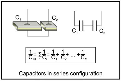
C_total = 1 / [(1/C1) + (1/C2) + (1/C3) + …]
This formula highlights that the total capacitance is inversely proportional to the sum of the reciprocals of individual capacitances. When capacitors are in series, their voltage ratings must also be taken into account to avoid overvoltage.
Applications
Series capacitors are instrumental when you need to reduce the overall capacitance in a circuit or when precise voltage division is necessary. Their use ensures that voltage distribution remains uniform across each capacitor.
Understanding the Series Formula
Let’s break down the series formula further:
- C_total: This represents the total capacitance when capacitors are connected in series.
- C1, C2, C3, …: These variables represent the capacitance values of each individual capacitor in the series.
- 1/C1, 1/C2, 1/C3, …: These are the reciprocals of the individual capacitances.
HSN code for Capacitors explained
The Harmonized System of Nomenclature (HSN) code is a globally recognized system for classifying goods in international trade. It’s an essential tool used to streamline the process of categorizing products, facilitating cross-border transactions, and ensuring uniformity in taxation and trade regulations.
The specific HSN code for capacitors can vary depending on factors like the type of capacitor, its intended use, and its characteristics.
Example HSN Codes for Capacitors
To provide a practical understanding, here are a few example HSN codes for capacitors:
- Electrolytic Capacitors: HSN Code – 8532.10.00
- This code classifies electrolytic capacitors, which are commonly used in power supply circuits and audio equipment.
- Ceramic Capacitors: HSN Code – 8532.21.00
- Ceramic capacitors, known for their compact size, fall under this classification.
- Tantalum Capacitors: HSN Code – 8532.23.00
- Tantalum capacitors, known for their reliability, have their distinct HSN code.
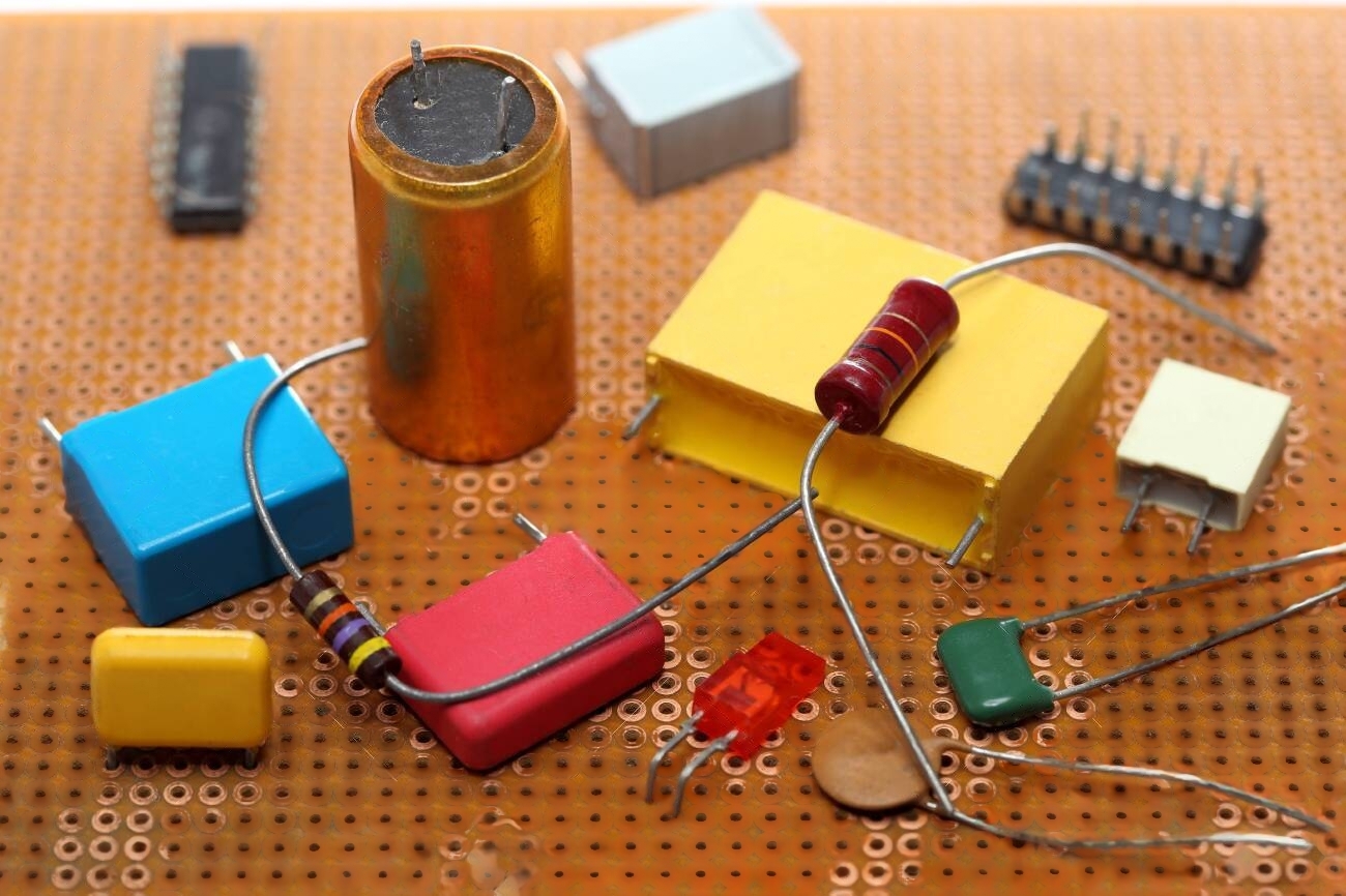
Exploring Various Capacitor Types and Their Uses
Capacitors come in a variety of types, each tailored to specific applications. Let’s take a closer look at different capacitor types and their practical uses.
- Ceramic capacitors
- Electrolytic Capacitor
- Decoupling Capacitor
- SMD Capacitor
- Tantalum Capacitor
- Film capacitor
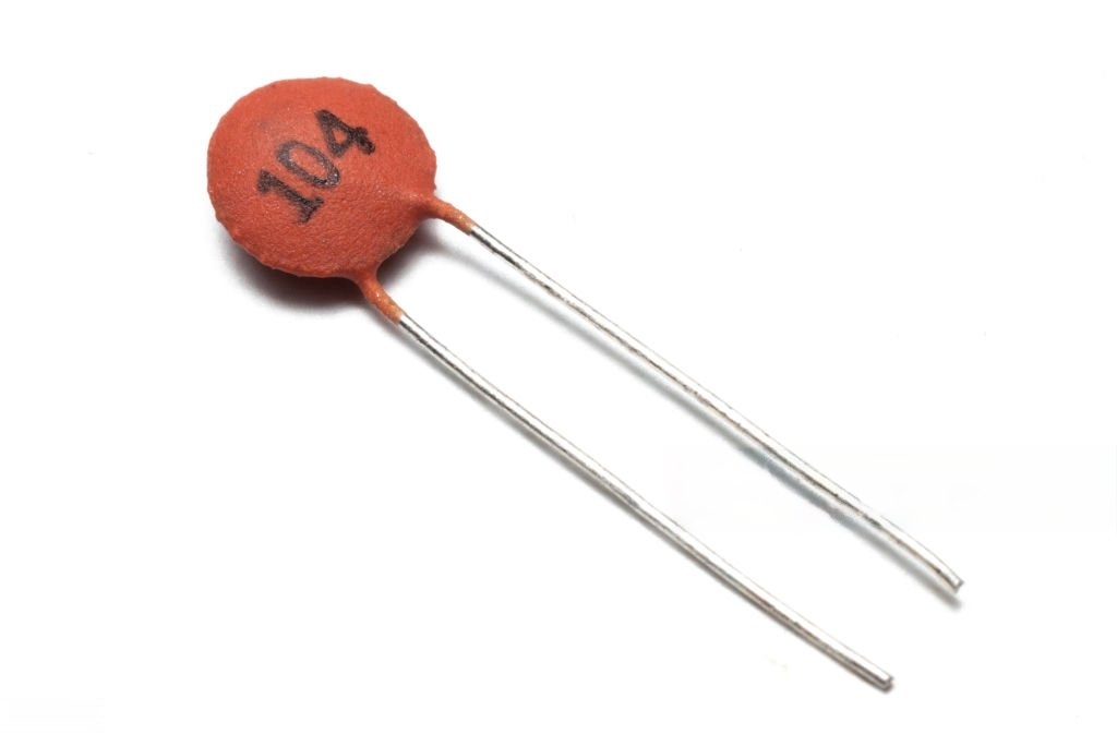
Ceramic Capacitors
Ceramic capacitors consist of two conductive plates separated by a ceramic dielectric material. This dielectric material is typically composed of ceramic compounds like barium titanite or various other ceramic formulations.
The choice of dielectric affects the capacitor’s characteristics, including capacitance value and voltage rating.
Whether you’re using a smartphone or driving a car, chances are ceramic capacitors are quietly working behind the scenes, ensuring your devices operate smoothly and reliably.
Advantages of Ceramic Capacitors
- Small Size: Ceramic capacitors are incredibly compact, making them suitable for space-constrained applications, such as mobile devices and PCBs with densely populated components.
- Low Equivalent Series Resistance (ESR): They exhibit low ESR, which means they can rapidly charge and discharge, making them ideal for high-frequency applications.
- Low Equivalent Series Inductance (ESL): Ceramic capacitors have low ESL, reducing parasitic inductance and enabling efficient filtering of high-frequency noise
Types of Ceramic Capacitors
There are two primary types of ceramic capacitors:
- Multilayer Ceramic Capacitors (MLCCs): MLCCs are the most common type, consisting of multiple ceramic layers stacked together. They offer a wide range of capacitance values and are suitable for general-purpose applications.
- Ceramic Disc Capacitors: These are disk-shaped ceramic capacitors with wire leads. They are commonly used in high-voltage and high-frequency applications.
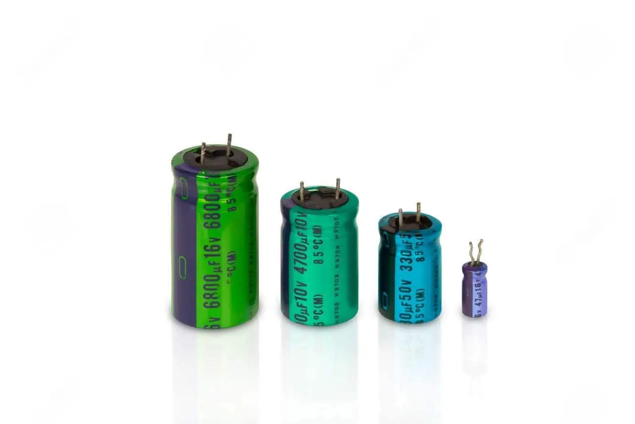
Electrolytic Capacitor
Electrolytic capacitors are a common and vital component in electronics, known for their high capacitance values and suitability for various applications. They play a crucial role in storing and delivering electrical energy in a wide range of electronic devices and circuits. Unlike many other types of capacitors, electrolytic capacitors utilize an electrolyte solution as part of their construction, which gives them their unique characteristics.
Applications of Electrolytic Capacitors
Electrolytic capacitors find applications in a wide range of electronic devices and circuits, including:
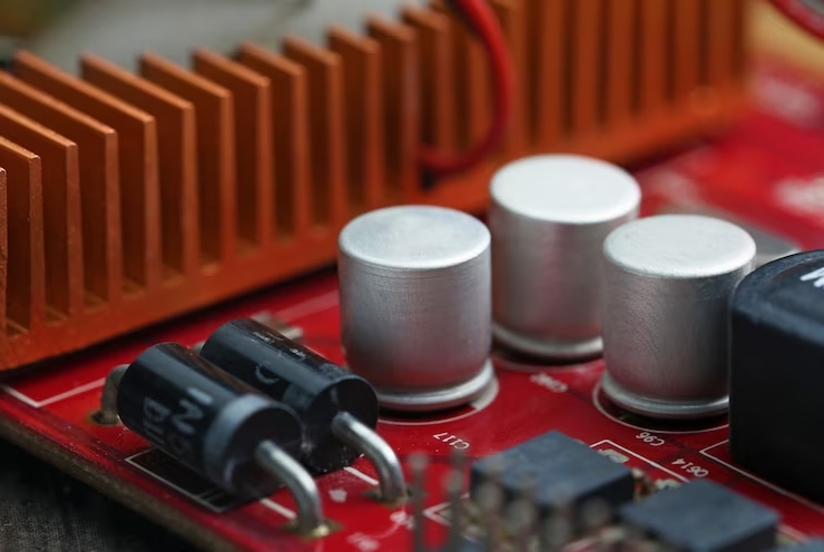
- Power Supplies: They are commonly used to smooth out voltage ripples in power supply circuits, ensuring a stable and continuous power output.
- Audio Electronics: Electrolytic capacitors are used in audio amplifiers and speakers to filter out low-frequency noise and enhance audio quality.
- Motor Starting: In some applications, electrolytic capacitors assist in starting electric motors by providing an initial surge of power.
Construction: Anode, Cathode, and Electrolyte
The construction of an electrolytic capacitor is distinctive. It consists of two conductive plates, typically made of aluminum, with a layer of oxide forming on the surface of one plate. This oxide layer acts as a dielectric. The other plate is immersed in an electrolyte solution, which is typically a conductive liquid or gel.
- Anode: The aluminum plate with the oxide layer is the anode. It serves as the positive electrode.
- Cathode: The other aluminum plate immersed in the electrolyte functions as the cathode, the negative electrode.
- Electrolyte: The electrolyte solution between the plates enhances the capacitor’s capacitance and performance.
Electrolytic capacitors are well-known for their ability to store large amounts of electrical charge, making them particularly useful in power supply circuits and audio electronics. Their capacitance values can range from microfarads (µF) to thousands of microfarads (mF), allowing them to handle significant energy storage.
Decoupling Capacitor
Decoupling capacitors, often referred to as bypass capacitors, are essential components in electronic circuits. They play a critical role in maintaining voltage stability and reducing noise in integrated circuits (ICs) and digital systems. These capacitors act as silent guardians, ensuring that sensitive components receive a stable and clean power supply, which is vital for the proper functioning of modern electronics.

Purpose of Decoupling Capacitors
Decoupling capacitors are primarily used to address two significant issues in electronic circuits:
- Voltage Regulation: Integrated circuits and digital components require a stable supply voltage to operate correctly. Fluctuations or noise in the power supply can lead to erratic behavior or malfunctions. Decoupling capacitors counteract these fluctuations by providing a local, low-impedance source of electrical energy.
- Noise Reduction: Electronic circuits generate electromagnetic interference (EMI) and radio-frequency interference (RFI) due to rapid changes in voltage and current. Decoupling capacitors absorb and filter out high-frequency noise, preventing it from propagating through the circuit and affecting other components.
How Decoupling Capacitors Work
Engineers strategically place decoupling capacitors on a Printed Circuit Board (PCB) near or in direct connection to sensitive components such as microcontrollers, ICs, or processors.
Their close proximity ensures that they can respond rapidly to changes in voltage demand.
- Capacitance Value: Decoupling capacitors typically have moderate capacitance values, often in the range of nanofarads (nF) to microfarads (µF). These values allow them to respond quickly to voltage fluctuations while providing sufficient energy storage capacity.
- Low Equivalent Series Resistance (ESR): A low ESR is crucial for decoupling capacitors because it ensures that they can supply energy rapidly without introducing resistance or voltage drop.
SMD Capacitor
Surface Mount Device (SMD) capacitors are compact and commonly used in modern PCB (Printed Circuit Board) designs. SMD capacitors are characterized by their small, flat, and rectangular shape. Their compact design allows for high component density on printed circuit boards (PCBs), making them ideal for space-constrained applications like smartphones, laptops, and IoT devices. The reduction in size also leads to shorter signal paths, minimizing parasitic inductance and improving high-frequency performance.
Advantages of SMD Capacitors
- Space Efficiency: Their compact size allows for efficient use of PCB real estate, enabling the design of smaller and sleeker electronic devices.
- High-Frequency Performance: Shorter lead lengths and reduced parasitic inductance make SMD capacitors suitable for high-frequency applications, such as RF (Radio Frequency) circuits.
Challenges and Considerations
While SMD capacitors offer numerous benefits, there are some considerations:
- Polarity: Some SMD capacitors, like tantalum and aluminum electrolytic types, are polarized and must be correctly oriented during assembly to avoid damage.
- Size Variations: SMD capacitors come in various case sizes (e.g., 0402, 0603, 0805), each with different dimensions and capacitance ratings. Careful selection is crucial to meet the circuit’s requirements.
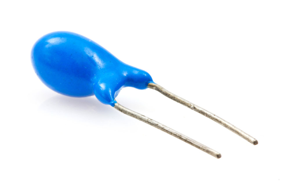
Tantalum Capacitor
Tantalum capacitors are a class of electrolytic capacitors known for their high capacitance, compact size, and excellent performance characteristics.
Construction and Working Principles
Tantalum capacitors consist of a tantalum pentoxide (Ta2O5) dielectric, which is a thin, insulating layer sandwiched between a tantalum powder anode and a conductive cathode. The tantalum pentoxide dielectric enables high capacitance values in a small form factor.
The working principle is similar to other capacitors, where the dielectric material between the plates stores and releases electrical energy.
Tantalum capacitors exhibit polarization, signifying a specific orientation, and reversing the polarity can result in damage or catastrophic failure.
Types of Tantalum Capacitors
Tantalum capacitors come in various types, each tailored to specific applications:
- Solid Tantalum Capacitors: These are the most common type and consist of a tantalum pellet, tantalum pentoxide dielectric, and a cathode terminal. A wide range of applications employs them, spanning from consumer electronics to aerospace.
- Tantalum Polymer Capacitors: These capacitors use a conductive polymer electrolyte instead of a liquid electrolyte, offering lower ESR and improved performance in high-frequency applications.
Film capacitor
The core of a film capacitor’s design is its dielectric material. Unlike electrolytic capacitors, film capacitors employ non-polarized dielectrics, which means they do not have a specific orientation, offering flexibility in their usage.
The dielectric material in film capacitors is typically made of materials like polyester (PET), polypropylene (PP), or polyethylene (PE).
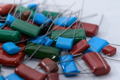
Film capacitors are prized for their precision in capacitance values and their excellent tolerance, often within a ±1% range.
They exhibit low dielectric absorption, which means they can charge and discharge rapidly without significant energy loss. This characteristic is especially valuable in applications demanding quick response times and minimal energy dissipation.
Applications
- Signal Processing: Film capacitors are vital in audio circuits, contributing to sound quality by fine-tuning the resonance and filtering characteristics.
- Motor Control: They are used in motor run and start capacitors to optimize the performance and reliability of electric motors.
- Energy Storage: Film capacitors are used in various energy storage applications, including renewable energy systems and uninterruptible power supplies (UPS).
In Summary
As we’ve seen, capacitors are indispensable in modern electronics, contributing to the functionality and reliability of numerous devices.
By now, you should have a solid foundation for understanding capacitors and their role in the world of electronics. Whether you’re a beginner or a seasoned enthusiast, this knowledge will serve you well in your electronic endeavors.
In conclusion, capacitors are the unsung heroes of the electronics world. They store energy, stabilize voltage, and enable countless electronic devices to function seamlessly. Understanding the types, functions, and formulas related to capacitors equips you with valuable knowledge for both theoretical understanding and practical application in your electronic projects.