In this guide, You will learn 6 Simple Ways To Blink Arduino LED by using:
Table Of Contents :
- Delays
- Counters
- Millis Function
- Watchdog Timer Interrupt
- Timer Interrupt
- Hardware Timer Toggle
- Conclusion
We will guide you from start to end so that you can blink your first LED.
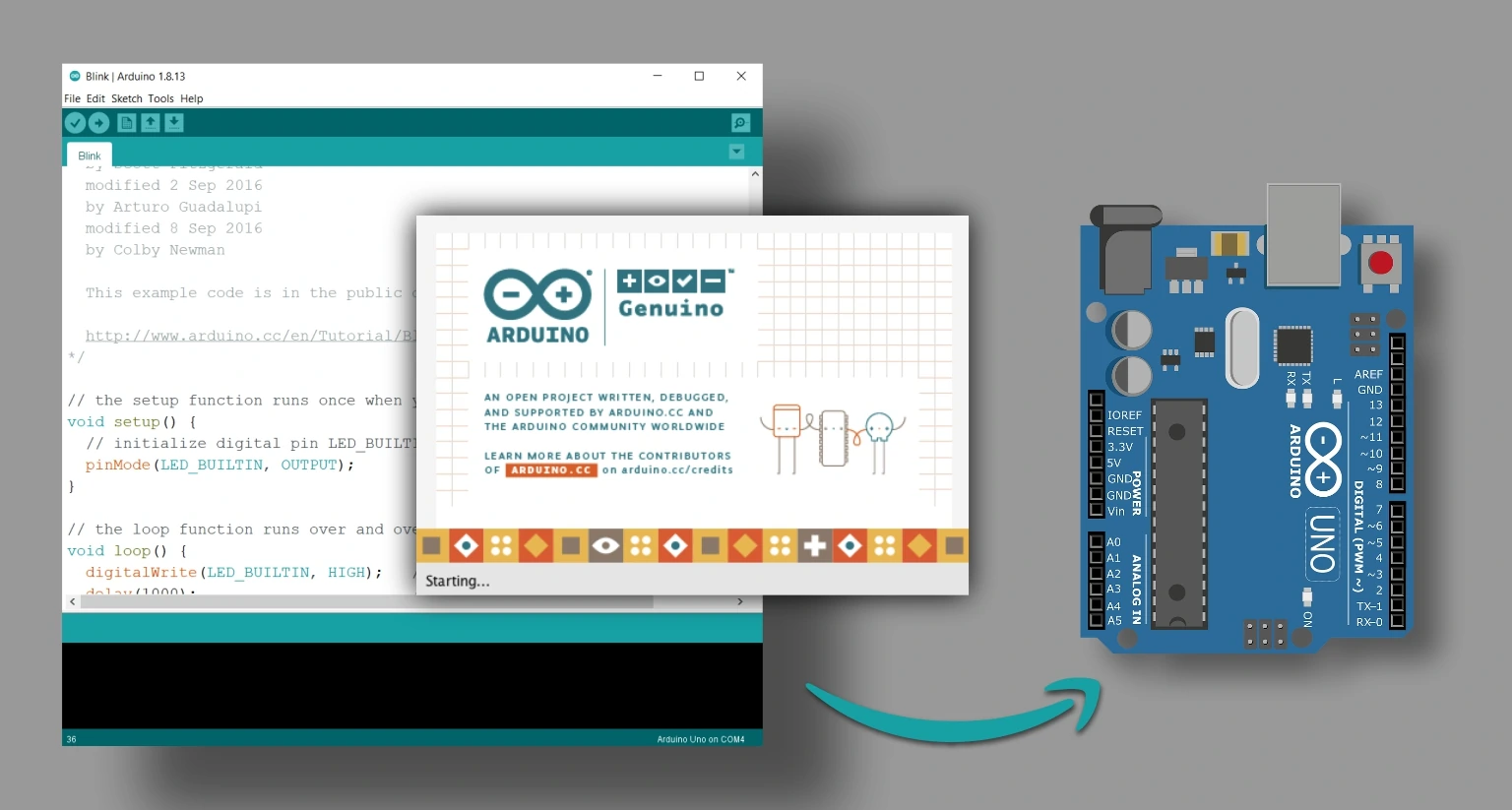
If you are not familiar with Arduino IDE then check our guide on-
❑ Getting Familiar With Arduino IDE
Let’s start by choosing the correct resistor value for our LED.
How To Calculate LED Resistor Value?
Calculating LED resistor value is very simple if we use the thumb rule for a basic calculation. We can easily calculate the LED resistor value using the Kirchhoff voltage law known as KVL and ohms law.
Don’t scratch your head; we need to figure out just three things:
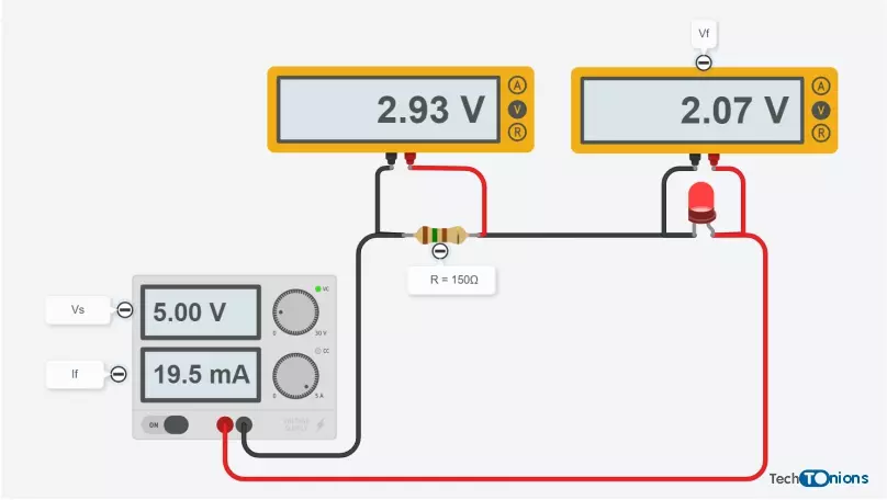
- That LED consumes voltage in another way, LED has forward voltage drop Vf which is around 2.2v for most LED’s. (But it vary between 1.8v to 2.5v).
- What is our supply voltage Vs? Most of the Arduino board works on 5V, So Vs=5V.
- Last we will require a forward current If of the LED. Forward Current is directly proportional to LED brightness. Let me simply divide in three-part Bright If=20mA, Medium If=15mA, Low If=10mA.
Put three values in the formula, and we will get the resistor R-value in ohms.


We have calculated the resistor value with 5V as the source voltage, and we want a forward current of less than 20 mA, so our current limiting resistor value will be 150 ohms.
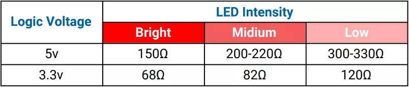
Still don’t want to calculate the current limiting resistor value?
Don’t worry, have precalculated LED resistor values required for both 5V (Arduino UNO, Nano, Mega) and 3.3V (Arduino mini, Due, Zero, ESP32, ESP8266, STM32) logic level controllers. Just follow our LED resistor table.
Now let’s blink our LED using different methods. Before starting, we are assuming that you have a little bit of knowledge about using Arduino and know how to upload code in Arduino.
Here are some of the simplest way to Blink Led in Arduino also code for quick solution.
1. LED Blink Using Delay.
Blinking LED in Arduino using the delay function is the simplest method among all others. This method is easy to understand yet, have some cons using this method stick around; we will discuss that soon.
So below is the Arduino Led blink code for every 1-second using delays.
/*
  Code written by: Dharmik
  Basic LED blink code using Delay
  Code uses 924 bytes of program memory and Global variables use 9 bytes.
  Find more on www.TechTOnions.com
*/

#define LED 13 // Defining an LED variable as 13 because our LED is connected to pin 13
void setup() {
  pinMode(LED, OUTPUT); // Set LED pin as OUTPUT
}

void loop() {
  digitalWrite(LED, HIGH);    // turn LED ON by writing HIGH (Sending 5v to pin 13)
  delay(1000);                       // wait for a second
  digitalWrite(LED, LOW);     // turn LED OFF by writing LOW (Sending 0v to pin 13)
  delay(1000);                       // wait for a second
}
To Simulate above code click open simulator button given below
Let’s understand this simple blinky code:
#define LED 13 // Defining an LED variable as 13 because our LED is connected to pin 13
We will define the digital pin used for our LED in our code. For this example, we have used digital pin 13. Therefore, using “LED” to define digital pin 13. So now onward in our code, we will represent pin 13 as LED.
void setup() {
  pinMode(LED, OUTPUT); // Set LED pin as OUTPUT
}
Now we will define our digital pin as an output pin in the void setup function.
void loop() {
  digitalWrite(LED, HIGH);    // turn LED ON by writing HIGH (Sending 5v to pin 13)
  delay(1000);                       // wait for a second
  digitalWrite(LED, LOW);     // turn LED OFF by writing LOW (Sending 0v to pin 13)
  delay(1000);                       // wait for a second
}
In the void loop, our code will run repeatedly:
We want to blink our LED in Arduino at an interval of 1 second. Firstly, we will make the LED pin state HIGH by using the digitalWrite function. By doing this, we are sending +5V to pin-13. Due to that, our LED will turn ON.
After that, we will wait for 1-second to do so we will use the delay function. We have used here delay(1000); because the delay function needs input in a millisecond. (1000mS = 1S).
Then, turn OFF our LED by setting the pin state to LOW. By doing this, we are sending 0V to pin-13. Due to that, our LED will turn OFF.
Again we will wait for 1 second. And after that, the code repeats from starting. Hence, our LED will blink forever.
Why we should avoid using Delay in our code?
As a beginner, using delay is fine as it’s simple to use and easy to understand. But the delay function will block your code for that particular time. As a result, our controller sits ideal and does nothing for that amount of time.
Think like this, if we want to glow LED when we press a button. And our code has a 2-second delay in it.
So for 2 seconds, it will not detect any change in the button press; therefore, the button press is skipped, and the controller takes no action.
2. Blink LED using Counters:
Using counters is the best method for beginners as it is simple as using the delay method and, this method will not block your code.
/*
  Date: 23-01-21
  Code written by: Dharmik
  LED blink code using a counter
  Code is non blocking code
  Code uses 810 bytes of program memory and Global variables use 13 bytes
  Find more on www.TechTOnions.com
*/

#define LED 13    // Defining an LED variable as 13 because our LED is connected to pin 13
long counter = 0; // Defining counter variable for counting

void setup() {
  pinMode(LED, OUTPUT); // Set LED pin as OUTPUT
}

void loop() {

  counter++;                 // will increment counter by 1
  if (counter == 100000)     // Check if counter value reach to 100000
  {
    digitalWrite(LED, HIGH); // turn LED ON by writing HIGH (Sending 5v to pin 13)
  }
  else if (counter == 200000) // Check if counter value reach to 200000
  {
    counter = 0;             // making counter value to 0
    digitalWrite(LED, LOW);  // turn LED OFF by writing LOW (Sending 0v to pin 13)
  }
  //Code is non blocking you can add your loop code after this
}
How code works:
#define LED 13    // Defining an LED variable as 13 because our LED is connected to pin 13
long counter = 0; // Defining counter variable for counting
We will start with defining digital pin 13 as “LED”.
Additionally, we will require a counter variable to store the count values thus, declaring the counter as a long Data type.
void setup() {
  pinMode(LED, OUTPUT); // Set LED pin as OUTPUT
}
Next, in the void setup function, we will set our pin as an OUTPUT pin.
void loop() {

  counter++;                 // will increment counter by 1
  if (counter == 100000)     // Check if counter value reach to 100000
  {
    digitalWrite(LED, HIGH); // turn LED ON by writing HIGH (Sending 5v to pin 13)
  }
  else if (counter == 200000) // Check if counter value reach to 200000
  {
    counter = 0;             // making counter value to 0
    digitalWrite(LED, LOW);  // turn LED OFF by writing LOW (Sending 0v to pin 13)
  }
  //Code is nonblocking you can add your loop code after this
}
Now inside our loop function, we will increment the counter variable each time loop executes.
After that, we will check our counter value with a conditional statement like if.
Therefore when the counter value reaches 100000, we will turn ON led using the digitalWrite function. And when it becomes 200000, we will turn OFF led and, now we will reset our counter value back to 0 so it can again increment and like this counter will blink led.
Hence, this method is simple to use and does not block our code, but we need to consider one thing before using this method: LED blink timing will not be precise. Because our code size may vary and loop execution time depends on the line of code and what else we do in a loop.
Therefore, this method is proper, but it will require some tweaks in choosing the perfect counter-compare value as per your code and requirement.
3. LED Blink in Arduino Using Millis Function:
Blinking an LED using the millis function is the most used method when it comes to doing multiple tasks at the same time using Arduino.
Understanding this method is a little tricky as compared to the above two methods.
Let’s first look at our Millis blink Led code.
/*
  Date: 23-01-21
  Code writen by: Dharmik
  LED blink code using millis
  Code is non blocking code
  Code uses 866 bytes of program memory and Global variables use 14 bytes
  Find more on www.TechTOnions.com
*/
#define LED 13                  // Defining an LED variable as 13 because our LED is connected to pin 13
unsigned long previousMillis;   // variable for comparing millis counter
bool ledState = false;       // will determine current led state
void setup() {
  pinMode(LED, OUTPUT);         // Set LED pin as OUTPUT
}

void loop() {
  if (millis() - previousMillis >= 1000)  // check that 1000ms is pass
  {
    if (ledState == false) {              // check the leddState and toggle it.
      ledState = true;
    }
    else {
      ledState = false;
    }
    digitalWrite(LED, ledState);          // Set LED state to ledState
    previousMillis = millis();            // set previousMillis to current millis
  }
}
Arduino has an inbuild function name “millis()” By calling this function, it gives the current milliseconds value.
The value of This function keeps incrementing as time passes on. And the function value goes overflow approx after 50 days.
How Code Works:
#define LED 13                  // Defining an LED variable as 13 because our LED is connected to pin 13
unsigned long previousMillis;   // variable for comparing millis counter
bool ledState = false;       // will determine current led state
For this example, we have declared two more variables along with an LED pin declaration.
ledState variable is used here to store the existing state of the LED.
Also, we have previousMillis as unsigned long as it will store time in a millisecond from the millis function.
Inside the setup function, we have just defined the LED pin state as OUTPUT.
if (millis() - previousMillis >= 1000) // check that 1000ms is pass
Inside the void loop, we have the main logic written in the if statement.
Let’s understand this by considering the previousMillis value to be 0 when we power ON the Arduino.
Now the millis function will be incrementing as time pass on, so the if condition that we have used checks the difference between the current time and the last time, and if the difference is greater, then 1000 means 1 second (1000mS = 1S).
if (millis() - previousMillis >= 1000)  // check that 1000ms is pass
  {
    if (ledState == false) {              // check the leddState and toggle it.
      ledState = true;
    }
    else {
      ledState = false;
    }
    digitalWrite(LED, ledState);          // Set LED state to ledState
    previousMillis = millis();            // set previousMillis to current millis
  }
Therefore at every 1 Second, this condition will be satisfied and don’t forget to store the current value of time as the last value. In our case, we need to write “previousMillis = millis();” inside the if condition.
The rest is pretty straightforward inside the if condition we check the ledState variable and change its value from true to false and vice versa.
Afterward, we are setting the LED pins output equal to the ledState.
So this way, the LED in Arduino will toggle every 1 Second.
Using the millis method has its advantages. As it is non-blocking, you can add your codes along with this LED blink code.
Moreover, it is more accurate in terms of timing accuracy than the counter method, but it requires more program memory on the other hand.
4. Blink LED in Arduino Using Watchdog Timer Interrupt:
All microcontrollers have timers block in their architecture, and the Watchdog timer is one of them.
We can use Watchdog timers to blink our LED.
Watchdog Timers are not designed to blink an LED; they are designed to serve different functionality to know more about watchdog timers and their usage check here.
Let’s head over to our code.
/*
  Date: 23-01-21
  Code written by: Dharmik
  LED blink code using Watchdog timer interrupt
  Code is non-blocking code and tested on Arduino UNO, Nano, Mega
  Code uses 810 bytes of program memory and Global variables use 10 bytes
  Find more on www.TechTOnions.com
*/

#include <avr/wdt.h>                                     //include avr Watchdog timer liberary
#define LED 13                                                //define LED pin as 13
boolean ledState = false;                                     //determines current state of led

void setup() {
  pinMode(LED, OUTPUT);                                       //Set LED pin as an OUTPUT
  cli();                                                      //Disable all interrupt occurring
  WDTCSR = (1 << WDCE) | (1 << WDE);                          //enable Watchdog interrupt

  /********************************************************************************************/
  //Uncomment any one time interval as per your requirenment

  //WDTCSR = (1 << WDIE);                                                                   //16ms
  //WDTCSR = (1 << WDIE) | (1 << WDP0);                                          //32ms
  //WDTCSR = (1 << WDIE) | (1 << WDP1);                                          //64ms
  //WDTCSR = (1 << WDIE) | (1 << WDP1) | (1 << WDP0);                  //0.125s
  //WDTCSR = (1 << WDIE) | (1 << WDP2);                                          //0.25s
  //WDTCSR = (1 << WDIE) | (1 << WDP2) | (1 << WDP0);                  //0.5s
  WDTCSR = (1 << WDIE) | (1 << WDP2) | (1 << WDP1);                     //1s
  //WDTCSR = (1<<WDIE)| (1<<WDP2) | (1<<WDP1) | (1 << WDP0);  // 2s
  //WDTCSR = (1<<WDIE)| (1<<WDP3);                                               //4s
  //WDTCSR = (1 << WDIE) | (1 << WDP3) | (1 << WDP0);                  //8s

  /*******************************************************************************************/

  sei();                                                      //Enable interrupts
}

void loop() {
  // put your main code here, to run repeatedly:
}


ISR(WDT_vect) {                                    // Watchdog interrupt vector
  if (ledState)                                    //check if ledstate is true then convert to false
  {
    ledState = false;
  }
  else                                             // if ledstate is false then this make it true
  {
    ledState = true;
  }
  digitalWrite(LED, ledState);                    //Set LED pin state as per ledState
}
Note:- Watchdog timer is not that accurate, So if you have any time-critical application, don’t use the watchdog timer.
How Code Works:
#include <avr wdt.h> //include avr Watchdog timer liberary
To use Watchdog Timers with Arduino IDE, we have to call one of the preinstalled AVR library names as avr/wdt.h
#define LED 13                                                //define LED pin as 13
boolean ledState = false;                                     //determines current state of led
After that, we will define an LED pin connected to digital pin 13. (you can change 13 as per your connection) Along with that, also a boolean variable name as ledState which will store LED’s current state.
  pinMode(LED, OUTPUT);                                       //Set LED pin as an OUTPUT
  cli();                                                      //Disable all interrupt occurring
  WDTCSR = (1 << WDCE) | (1 << WDE);                          //enable Watchdog interrupt
Moving toward our setup function. Firstly we will set our led pin as an OUTPUT pin.
Afterward, we have to use the library function cli(); to disable all interrupts. We can ignore this, but it is good practice to disable interrupt before setting new interrupt registers.
Then we have set WDCE and WDE bits to 1 inside the WDTCSR register to enable the watchdog timer in interrupt mode.
To do so following syntax is used WDTCSR = (1 << WDCE) | (1 << WDE);
  //WDTCSR = (1 << WDIE);                                                                   //16ms
  //WDTCSR = (1 << WDIE) | (1 << WDP0);                                          //32ms
  //WDTCSR = (1 << WDIE) | (1 << WDP1);                                          //64ms
  //WDTCSR = (1 << WDIE) | (1 << WDP1) | (1 << WDP0);                  //0.125s
  //WDTCSR = (1 << WDIE) | (1 << WDP2);                                          //0.25s
  //WDTCSR = (1 << WDIE) | (1 << WDP2) | (1 << WDP0);                  //0.5s
  WDTCSR = (1 << WDIE) | (1 << WDP2) | (1 << WDP1);                     //1s
  //WDTCSR = (1<<WDIE)| (1<<WDP2) | (1<<WDP1) | (1 << WDP0);  // 2s
  //WDTCSR = (1<<WDIE)| (1<<WDP3);                                               //4s
  //WDTCSR = (1 << WDIE) | (1 << WDP3) | (1 << WDP0);                  //8s

  sei();                                                      //Enable interrupts
The next step will be to set the Watchdog interrupt time interval.
We can not set the time we like as the watchdog timer only allows us to set timing as per the table given in the datasheet.

To set different time intervals, we have to set different bits for WDP0, WDP1 & WDP2 as per the table.
Additionally, We will enable interrupt by setting the WDIE bit inside the WDTCSR register along with the time setting.
Lastly, we will enable all interrupts by calling library function sei();
 ISR(WDT_vect) {                                    // Watchdog interrupt vector
  if (ledState)                                    //check if ledstate is true then convert to false
  {
    ledState = false;
  }
  else                                             // if ledstate is false then this make it true
  {
    ledState = true;
  }
  digitalWrite(LED, ledState);                    //Set LED pin state as per ledState
}
Now we will define the ISR function name as WDT_vect, which will be called on every watchdog timer interrupt.
Inside the interrupt function, we will add out led toggle logic similar to what we use in milling method.
Note:- Do not add delays or any time-consuming code inside the ISR functions like Serial prints.
This method is also a non-blocking method, and also void loop will be empty to add your code running parallel to the LED blink code.
5. LED Blink in Arduino Using a Timer Interrupt:
Arduino UNO has 3 timers: timer0, timer1 & timer2. Timers come in handy when an application needs high timing accuracy. timer0 is already being used by the default millis() function in Arduino.
Therefore we will use timer1 to blink Arduino LED.
/*
  Date: 23-01-21
  Code written by: Dharmik
  LED blink code using timer interrupt
  Code is non blocking code and tested on Arduino UNO, Nano, Mega
  Code uses 880 bytes of program memory and Global variables use 10 bytes
  Find more on www.TechTOnions.com
*/

#define LED 13
boolean ledState = false;          //determines current state of led

void setup() {
  pinMode(LED, OUTPUT);
  TCCR1A = 0;                      //Reset Timer1 control Registor A

  bitClear(TCCR1B, WGM13);         //Set CTC mode
  bitSet(TCCR1B, WGM12);


  bitSet(TCCR1B, CS12);            //Set prescaler to 1024
  bitClear(TCCR1B, CS11);
  bitSet(TCCR1B, CS10);

  //Reset Timer1
  TCNT1 = 0;

  //set compare value
  //max value  (16bit Timer) = 65535
  /*******************************************
    To calculate compare value
    OCR1A = (time(s) * clock Freq.)/prescaler
    OCR1A = (1*16*10^6)/1024
  ********************************************/
  //OCR1A = 3906;     //for 0.25sec
  //OCR1A = 7812;    //for 0.5sec
  OCR1A = 15625;   //for 1sec
  //OCR1A = 31250;   //for 2sec

  bitSet(TIMSK1, OCIE1A); // Enable Timer1 compare interrupt
  sei();                  // Enable global interrupts
}

void loop() {
  // put your main code here, to run repeatedly:
}

ISR(TIMER1_COMPA_vect)
{
  if (ledState)                // check if ledstate is true then convert to false
  {
    ledState = false;
  }
  else                         // if ledstate is false then this make it true
  {
    ledState = true;
  }
  digitalWrite(LED, ledState); //Set LED pin state as per ledState
}
How Code Works:
 #define LED 13
 boolean ledState = false;          //determines current state of led
Similar to other methods, we will define the LED pin and Led state variable.
  //set compare value
  //max value  (16bit Timer) = 65535
  /*******************************************
    To calculate compare value
    OCR1A = (time(s) * clock Freq.)/prescaler
    OCR1A = (1*16*10^6)/1024
  ********************************************/
  //OCR1A = 3906;     //for 0.25sec
  //OCR1A = 7812;    //for 0.5sec
  OCR1A = 15625;   //for 1sec
  //OCR1A = 31250;   //for 2sec
This tutorial will not cover how to use Arduino timers; we will cover that in a separate tutorial in the future.
For now, you need to calculate the timer1 compare value.
As when the timer counter gets equal to compare value, it fires the timer interrupt.
Therefore you can easily calculate the OCR1A value as needed by using the formula given in our code.
Here we are using 15625 as an OCR1A value to set a 1-second interval. You can uncomment a different value if you want.
ISR(TIMER1_COMPA_vect)
{
  if (ledState)                // check if ledstate is true then convert to false
  {
    ledState = false;
  }
  else                         // if ledstate is false then this make it true
  {
    ledState = true;
  }
  digitalWrite(LED, ledState); //Set LED pin state as per ledState
}
We will add the ISR function name as TIMER1_COMPA_vect, which will be fired whenever the Timer1 counter reached the compare value in our case; it is 1second.
Inside the ISR function, we have the same logic for the LED toggle used in the previous method.
Note:- Do not add delays or any time consuming code inside ISR function like Serial prints.
This method is also non-blocking to run different code along with blink code in the void loop.
6. LED Blink With Hardware Timer Toggle:
This method is very similar to the timer interrupt method.
But this time, we will not use any interrupt; we will directly toggle the LED connected to Digital Pin 9
/*
  Date: 23-01-21
  Code written by: Dharmik
  LED blink code using hardware timer interrupt
  This method only work for Digital pin 9
  Code is non blocking code and tested on Arduino UNO, Nano
  Code uses 634 bytes of program memory and Global variables use 9 bytes
  Find more on www.TechTOnions.com
*/

#define LED 9
void setup() {
  pinMode(LED, OUTPUT);

  TCCR1A = 0;               //Reset Timer1 control Registor A

  bitClear(TCCR1B, WGM13);  //Set CTC mode
  bitSet(TCCR1B, WGM12);

  bitSet(TCCR1B, CS12);    //Set prescaler to 1024
  bitClear(TCCR1B, CS11);
  bitSet(TCCR1B, CS10);

  //set compare value
  //max value  (16bit Timer) = 65535
  /*******************************************
    To calculate compare value
    OCR1A = (time(s) * clock Freq.)/prescaler
    OCR1A = (1*16*10^6)/1024
  ********************************************/
  //OCR1A = 3906;     //for 0.25sec
  //OCR1A = 7812;    //for 0.5sec
  OCR1A = 15625;   //for 1sec
  //OCR1A = 31250;   //for 2sec

  //  OCR1A= 62500;
  bitSet(TCCR1A, COM1A0); // Toggle pin OC1A (9)
}

void loop()
{
}
How Code Works:
In this method also we will use timer1.
Therefore we have to calculate the value of OCR1A using the formula mentioned in the code.
The value of OCR1A will be 15625 for 1 second and can be changed as needed.
bitSet(TCCR1A, COM1A0); // Toggle pin OC1A (9)
Now we will set COM1A0 bit in the TCCR1A register so that it will toggle OC1A pin, which is digital pin 9 in Arduino UNO.
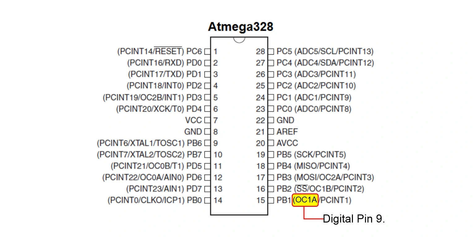 Note:- This method only works on digital pin 9.
This method is also non-blocking.
Check out all the new features in Arduino 2.0-beta that make it a modern IDE.
❑ Getting Smarter with Arduino IDE 2.0
Conclusion
We can Blink LED in Arduino with various methods or logic. Each method has its advantage and disadvantage. Therefore it depends on our application to which method to choose. So lastly, tell us your favorite method for blinking an LED in the comment section.
Mastering the art of LED manipulation opens up a world of possibilities. If you’re intrigued by the diverse applications of LEDs and want to explore various types of LEDs, head over to our in-depth Guide on Types of LEDs.


Nice tutorial
my favorite method for Blinking an Led :
1- Millis();
2- Counter
there is more simple than
ISR(TIMER1_COMPA_vect) { if (ledState) // check if ledstate is true then convert to false { ledState = false; } else // if ledstate is false then this make it true { ledState = true; } digitalWrite(LED, ledState); //Set LED pin state as per ledState }useISR(TIMER1_COMPA_vect) { ledState = !ledState; digitalWrite(LED, ledState); //Set LED pin state as per ledState }