Table Of Contents :
- What Is Operational Amplifier (OP-AMP)?
- Applications Of OP-AMPS
- Operational Amplifier Characteristics And Parameters
- Simple OP-AMP Rules To Remember
- Operational Amplifier Configuration
- Conclusion
What Is Operational Amplifier (OP-AMP)?
An operational amplifier is an integrated block of a circuit used to amplify week electrical signals(voltage).
It takes a differential voltage input and generates a single-ended voltage output.
OP-AMP is widely used in signal amplification or conditioning, filtering & performing mathematical operations such as adding, subtracting, differentiation, or integrating.
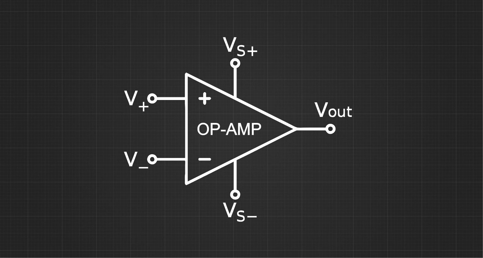
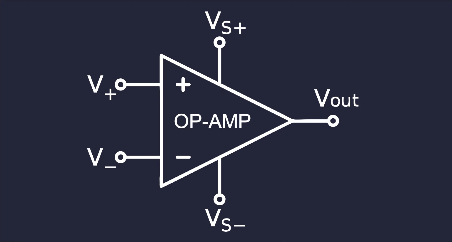
OP-AMP symbol is just a simple triangle with all input and output pins attached to it. There are two types of input of OP-AMP.
- Inverting input (V-).
- Non Inverting input (V+).
And one output pin along with two power supply pins Vs+ & Vs-.

Note:- You will often find in many OP-AMP-based schematic circuits the input pin location is swapped or the triangle orientation is changed, but all are valid symbol representations of OP-AMP.
Applications Of OP-AMPS
As discussed above, there are many applications of an operational amplifier. The operational amplifier is not used alone for any application, and mainly opamp will combine it with different electrical elements to achieve the desired outcomes.
We will discuss a few of the practical applications that are done with an OP-AMP.
Amplification Of An Input Signal
Here is a simple application with an audio signal coming out from any mobile device in the first case. The audio signal is small in amplitude and weak to drive any speakers and generate proper audible sound effects.
Therefore such application requires amplification of signal input, and therefore OP-AMP comes into the picture.

In the second case, we have added an OP-AMP to amplify the audio input signal, and now we get an amplified signal as an output, and now it can directly drive the speaker, and you can now listen to your favorite soundtrack.
Audio amplifiers are mostly used for such applications; they are specially designed OP-AMPs to deal with audio.
Filtering The Input Signal
For this application, in case one, there is a microphone where our friend says OK GOOGLE. The microphone signal picks up the noise from the environment, and now the signal has combined with noise and is directly sent to the microcontroller to process the audio signal.
The microcontroller will find a hard time processing such noise data, and it will not understand that someone is saying OK GOOGLE.
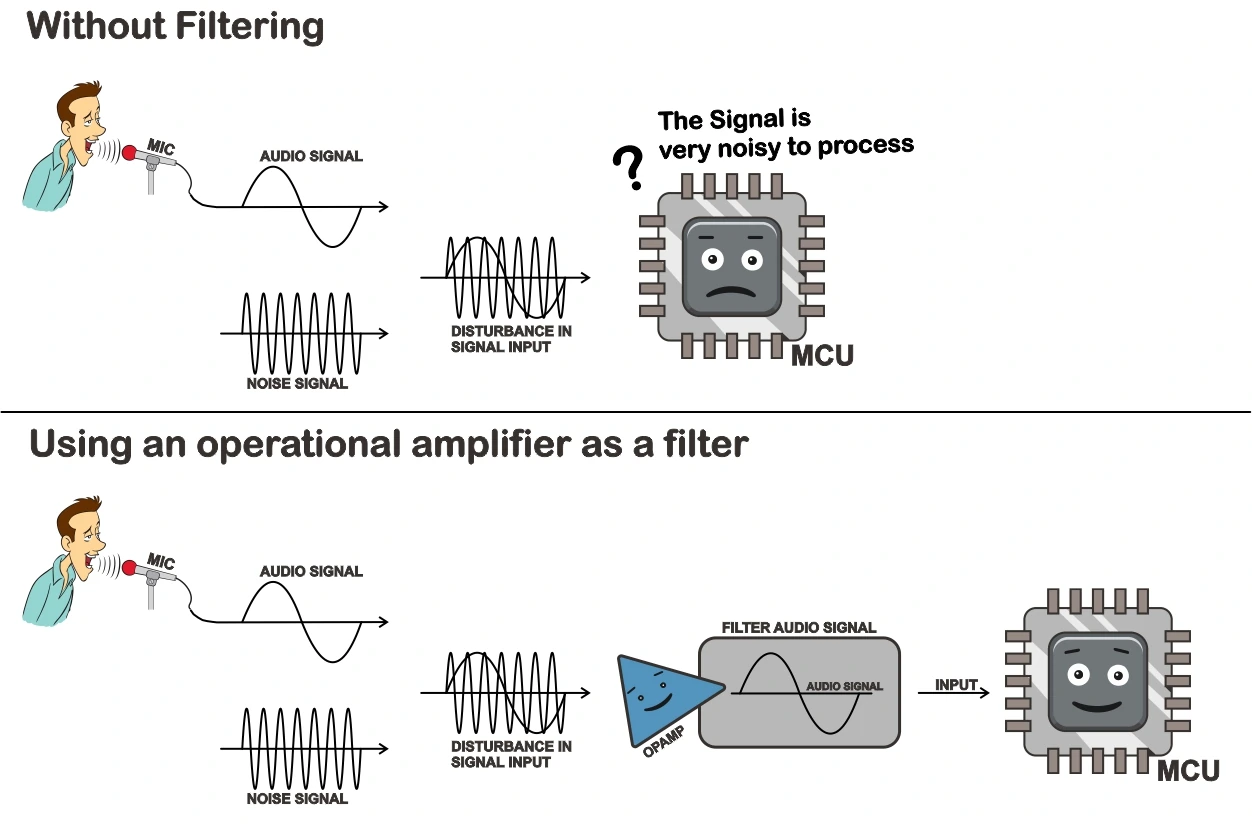
Now in the second case, we have used an operational amplifier as a filter. We can build filters like low-pass or high-pass filters based on OP-AMP.
Now it will filter out the noise signal out from the actual signal. And the microcontroller will now easily process the OK GOOGLE audio signal and can react accordingly.
Boosting Current Of Input Signal
In this application, in the first case, the sensor sends a voltage signal directly to the microcontroller’s input. Now, this particular sensor can only deliver very low current output.
These types of sensors have a high output impedance. If we connect them with a low input impedance circuit, this circuit will start drawing more current. The sensor cannot deliver that much current; hence the signal voltage will be change from its actual value.
Due to this, it will cause an error in the measurement of the signal.
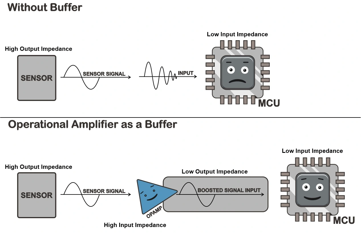
To solve such conditions, OP-AMP is used as a buffer. OP-AMP takes in very negligible current from input pins; hence, it has high input impedance and can deliver more current than the sensor output.
Therefore it will replicate the same input signal as an output signal and can deliver more current. This signal can be used to measure the input signal, and it will not cause an error due to loading.
Operational Amplifier Characteristics And Parameters
We will discuss a few important characteristics and parameters of an operational amplifier in a very simple form.
OP-AMP Gain
When you come across any OP-AMP-based circuit, you would have heard the term gain. Av or G denotes the gain of an OP-AMP.
The OP-AMP gain is a multiplying factor for an output voltage. The amount of amplification required on the output pin can be set by a gain of OP-AMP. In simple formula output of OP-AMP can be denoted as
Vout = G × Vin
let’s understand with a simple example if you set a gain of OP-AMP to 10. And you apply an input signal of 1V, the output signal voltage of OP-AMP will be 10V.
You can easily calculate gain with our easy to use
Stick around; we will discuss later how to set the proper gain of an OP-AMP.
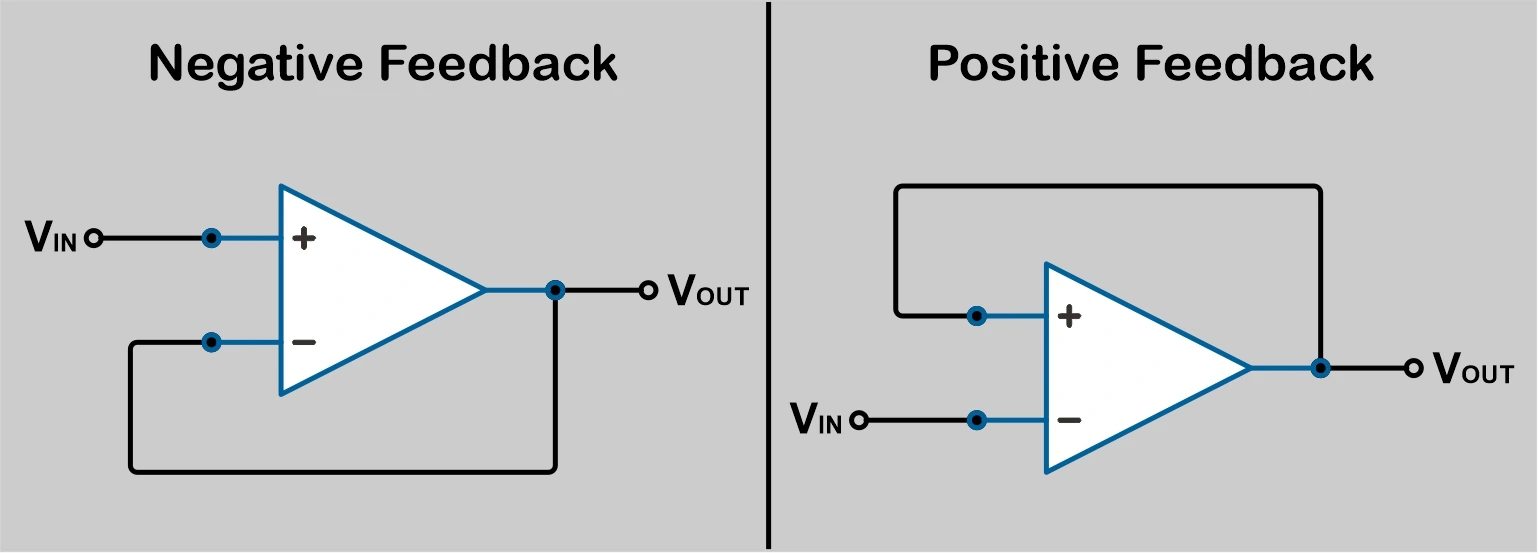
OP-AMP Feedback
Another term you will herd will be opamp feedback; it is just an output signal attached to one of the input pins of an OP-AMP directly or with a resistor network.
There are two types of feedback.
Negative Feedback – The output signal is connected with inverting input of OP-AMP. In most OP-AMP-based applications, negative feedback is used to improve the system’s stability by minimizing the noise, distortion and improving system bandwidth and input-output impedance.
Positive Feedback – The output signal is connected with the non-inverting input of OP-AMP.
Open-Loop Gain
Open-loop means no feedback is given in the operational amplifier. And when an operational amplifier is used in the open-loop configuration, its gain is extremely large (100,000+).
Therefore it is not recommended to use OP-AMP in open-loop configuration.
Except for comparators, as they are designed to work specifically in the open-loop configuration, we will cover more on comparators and differential amplifiers in upcoming guides.
Input Impedance
The input impedance of an operational amplifier is high. It is measured current between two inputs of an OP-AMP. And input impedance of the ideal OP-AMP is infinite, but in reality, there will be a small amount of leakage current flowing to the inputs.
Due to this, the OP-AMP has minimum impact on the loading condition of the source, as discussed in one of the applications above.
Output Impedance
The output impedance of an ideal operational amplifier is zero, but in reality, it has a very small value. And that value determines the current driving capability of an OP-AMP.
Frequency Response And Gain Bandwidth
An ideal opamp would have an infinite gain bandwidth it means it can maintain the output level with high gain values at any input signal frequency. But in reality, every OP-AMP will have a certain limitation on the gain regarding a signal frequency. Generally, the lower the gain you set, the higher the input frequency you can use.
Here is the open-loop gain vs frequency curve of a famous OP-AMP IC known as µA741.
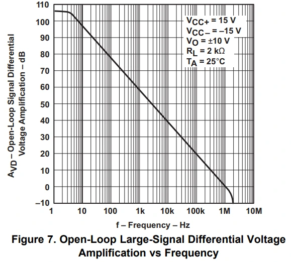
As we see at gain on 1 (0dB), the input signal frequency can go up to 1MHz, and at a gain of 10 (20dB), the input signal frequency can only go up to 100KHz.
Simple OP-AMP Rules To Remember
There are only two main rules that you need to remember when dealing with operational amplifiers. These two rules make it simpler to understand or build circuits based on OP-AMP. Rules are for an ideal OP-AMP.
Rule 1: No current will flow IN or OUT from the input pins of the operational amplifier.
Rule 2: The OP-AMP tries to keep both the inputs at the same voltage level when feedback is used.
Note:- Rules are for an Ideal OP-AMP, but there will be a tiny amount of leakage current flowing into input pins in reality.
Operational Amplifier Configuration
Multiple configurations can be done with an OP-AMP, based on your requirements. Here we will discuss the major configuration that is commonly used in many OP-AMP-based circuits.
We will additionally show you a simulation based on a particular configuration. Our schematic or simulation is done on the most commonly used OP-AMP IC 741. If you want to perform the same experiments, you can easily find LM741 or µA741.
Non – Inverting Configuration
In a non-inverting configuration, the input signal is given to a non-inverting terminal (+) of an OP-AMP. The output voltage will always be in-phase of the input signal applied, and therefore it is called a non-inverting amplifier.
The below image represents the non-inverting OP-AMP configuration.
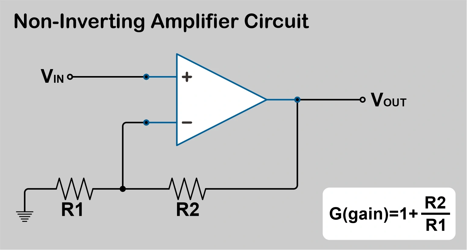
As per our rule-2 discussed above, the OP-AMP will always try to make both input voltage the same by changing its output accordingly. You can add a simple two resistor network to set the gain.
And therefore, for non-inverting configuration, the gain of an OP-AMP is derived as:
G = 1 + R2/R1
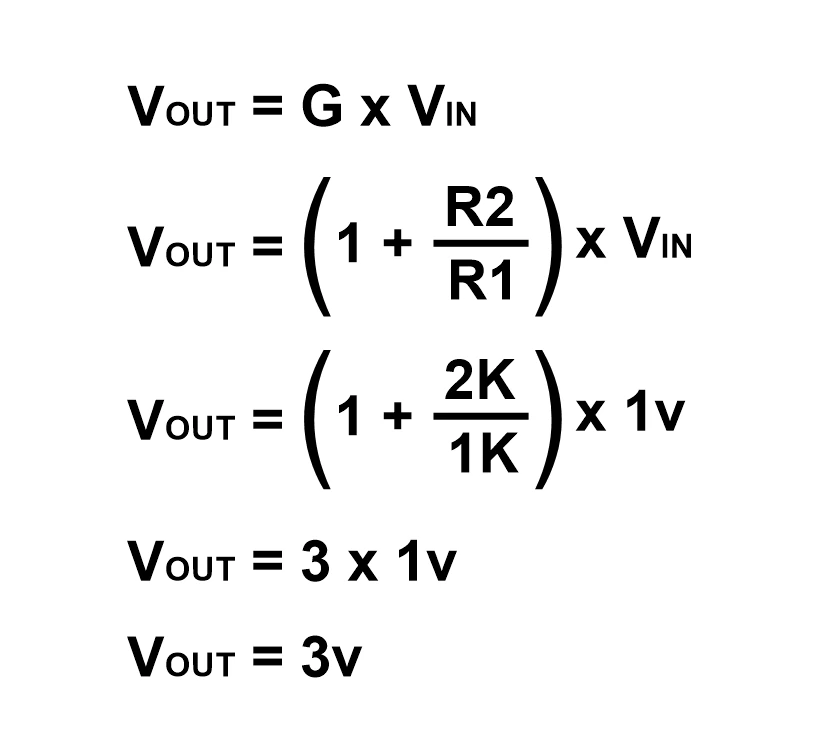
And as discussed above, the gain will be multiple of input voltage. Now we can easily derive output voltage as
VOUT=(1+R2/R1)×VIN
Based on the above circuit and formula, we have set a gain of 3 in LM741 using resistor values as R2=2k and R1=1K.
We have done a small simulation for a non-inverting amplifier circuit with a gain of 3.
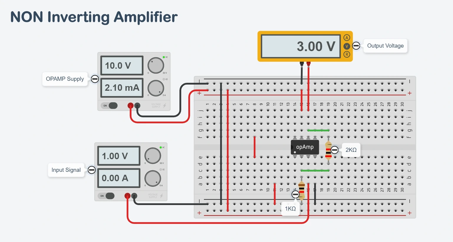
Therefore, when we apply 1V as an input signal to a non-inverting pin, we get an output of 3V due to the gain of 3.
To Simulate above code click open simulator button given below
We can easily calculate the output voltage as below with a gain setting.
Here is the schematic diagram that we have used for the above simulation.
Inverting Configuration
In an inverting configuration, the input signal is given to an OP-AMP inverting terminal (-). The output voltage will always be inverted to the input signal applied, and therefore it is called a non-inverting amplifier.
The below image represents the inverting OP-AMP configuration.
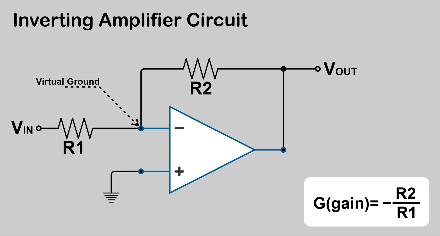
As per our rule-1 discussed above, there will be no current flowing into an input pin of an OP-AMP. The input current will be
Iin = Vin/(R1+R2)
And by rule-2, we know OP-AMP will always try to make both input voltage at the same level. The non-inverting input is solidly grounded means 0V; due to this, it will make inverting input pin voltage to 0V by setting the output accordingly. And as we have not connected the inverting input to the ground, the voltage level will still be 0V; therefore, this point is known as Virtual Ground.
We can add a simple two resistor network to set the gain. And therefore, for inverting configuration, the gain of OP-AMP is derived as:
G = – R2/R1
And as discussed above, the gain will be multiple of input voltage. Now we can easily derive output voltage as
VOUT=(-R2/R1)×VIN
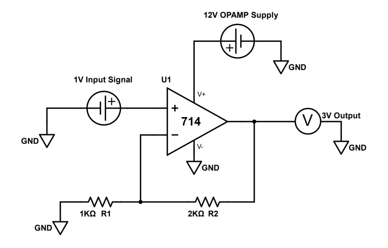
Based on the above circuit and formula, we have set a gain of 3 in LM741 using resistor values as R2=3k and R1=1K.
We have done a small simulation for an inverting amplifier circuit with a gain of 3.
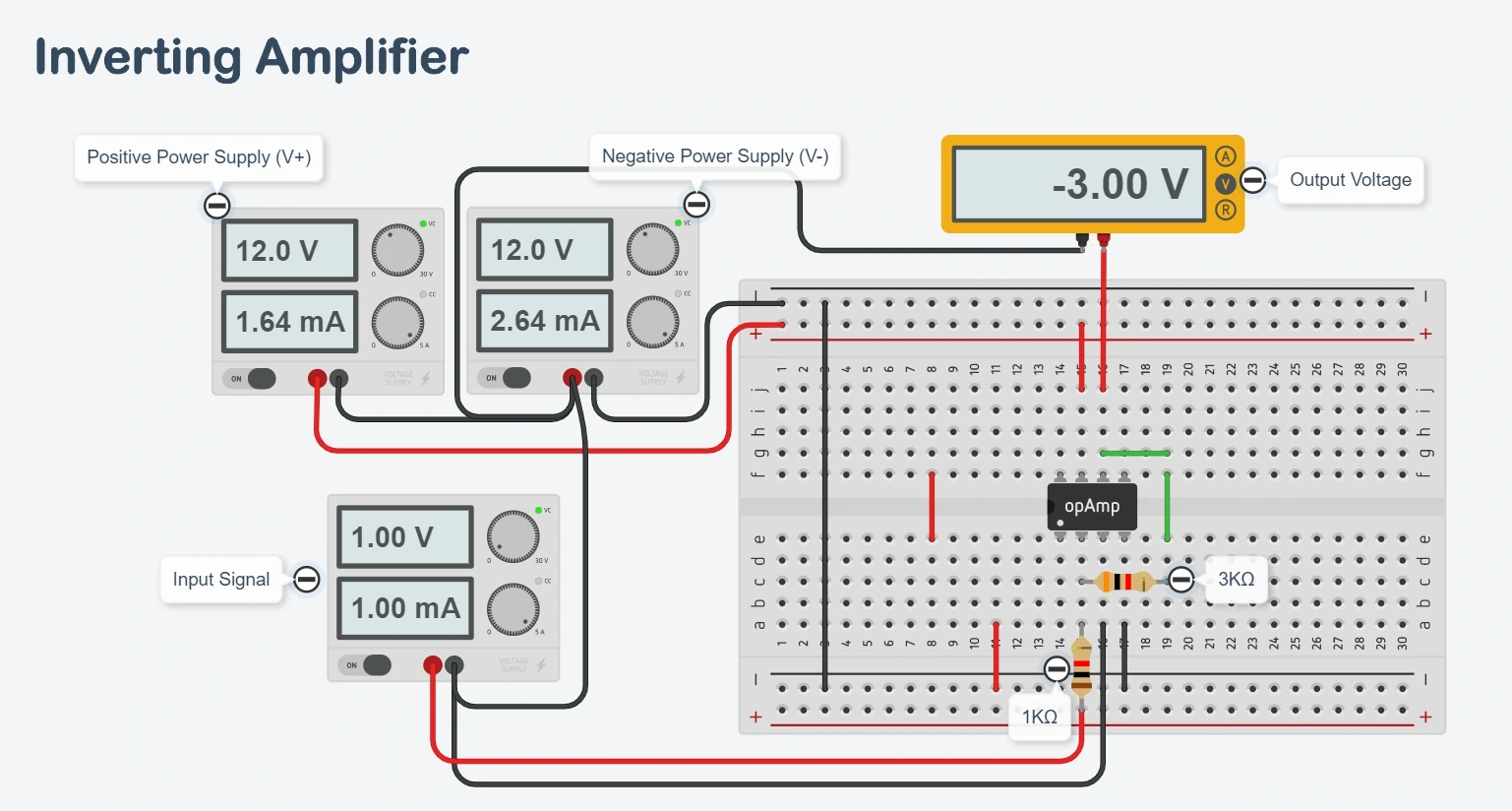
Therefore, when we apply 1v as an input signal to a non-inverting pin, we get an output of -3V due to the gain of 3.
Note:- For getting a negative output, it is mandatory to provide a negative power supply to the OP-AMP.
To Simulate above code click open simulator button given below
We can easily calculate the output voltage as below with a gain setting.

Here is the schematic diagram that we have used for the above simulation.

Voltage Follower (Buffer)
It is the most basic circuit, which mostly does not require any external components. Its main function is to replicate the input signal to the output pin of an OP-AMP. Due to the operational amplifier’s high input impedance and low output impedance capabilities act as a buffer.
The below image represents the voltage follower with OP-AMP.
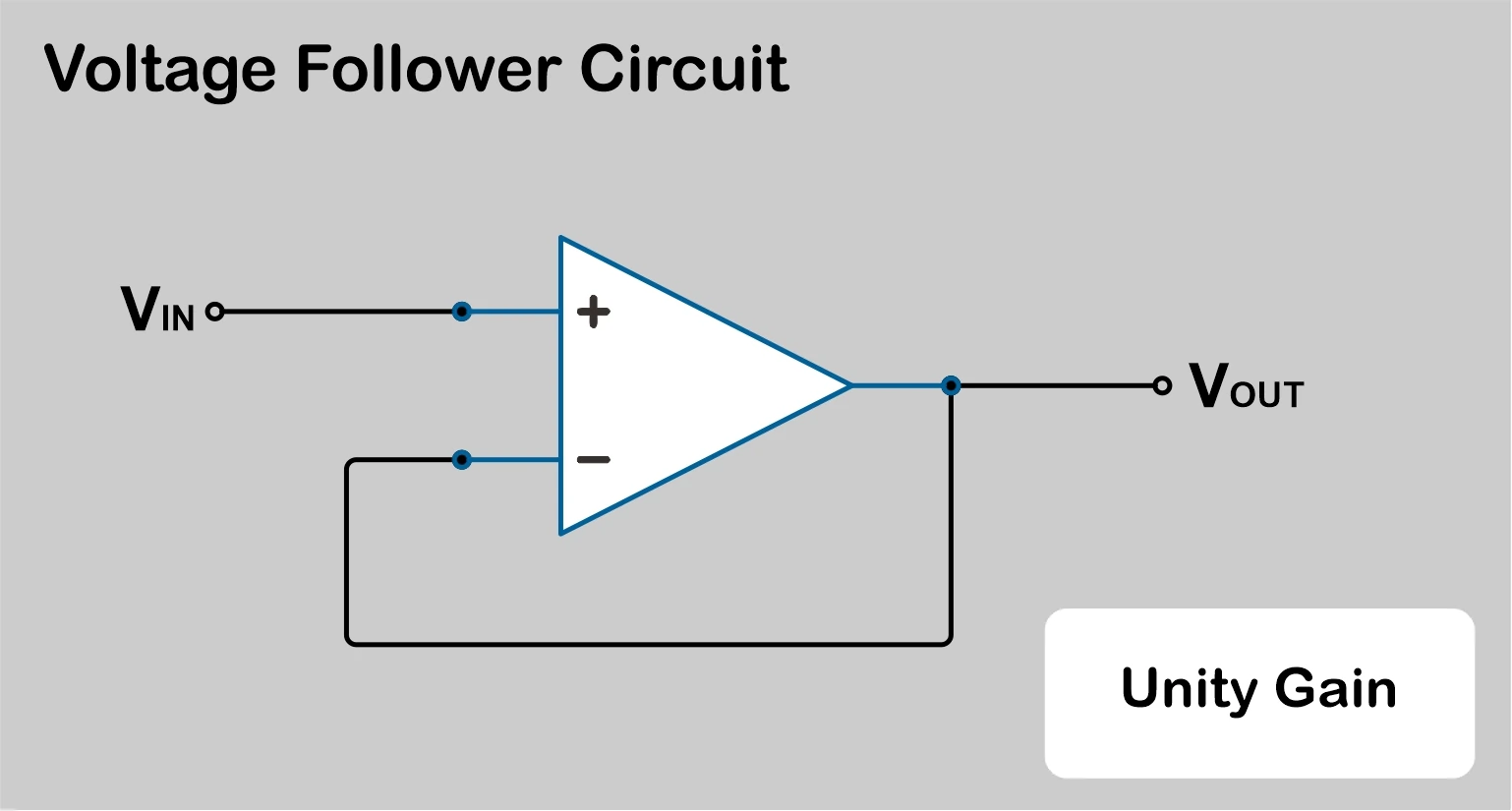
The output voltage will be equal to the input voltage signal. Therefore we can say it has a unity(1) gain. The output voltage will be.
Vout = Vin
We have done a simulation for a voltage follower using LM741 OP-AMP.
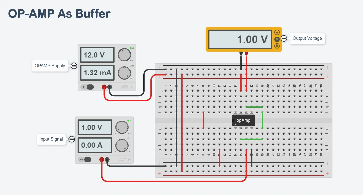
As we see, when we applied 1V as an input signal, we get exactly 1V from the output pin of OP-AMP.
To Simulate above code click open simulator button given below
Here is the schematic diagram that we have used for the above simulation.

There are more configurations such as comparator, summing, differential, integrator, and more. We will cover different configurations in upcoming guides.
Conclusion
We have learned different use-cases based on opamps, and additionally, we designed a simple OP-AMP circuit for understanding different configurations of an operational amplifier.
There are countless ways in which operational amplifiers are used in different analog circuits.
Want to learn more about operational amplifiers? Or want more analog projects? Then subscribe to our weekly newsletter.


Great illustration of analog electonics, thanks.
still, analog technology is more reliable than digital in some areas.
Thank you, Harry.
thank you for all informetion
Thank you, faiz.