Table Of Contents :
- Parts Required
- How To Program ESP32-CAM?
- Schematic Diagram
- Working Of ESP32-CAM Programmer Shield
- Let’s Start Building ESP32-CAM Programming Shield
- Programming ESP32-CAM With a DIY Shield
- Wrapping Up
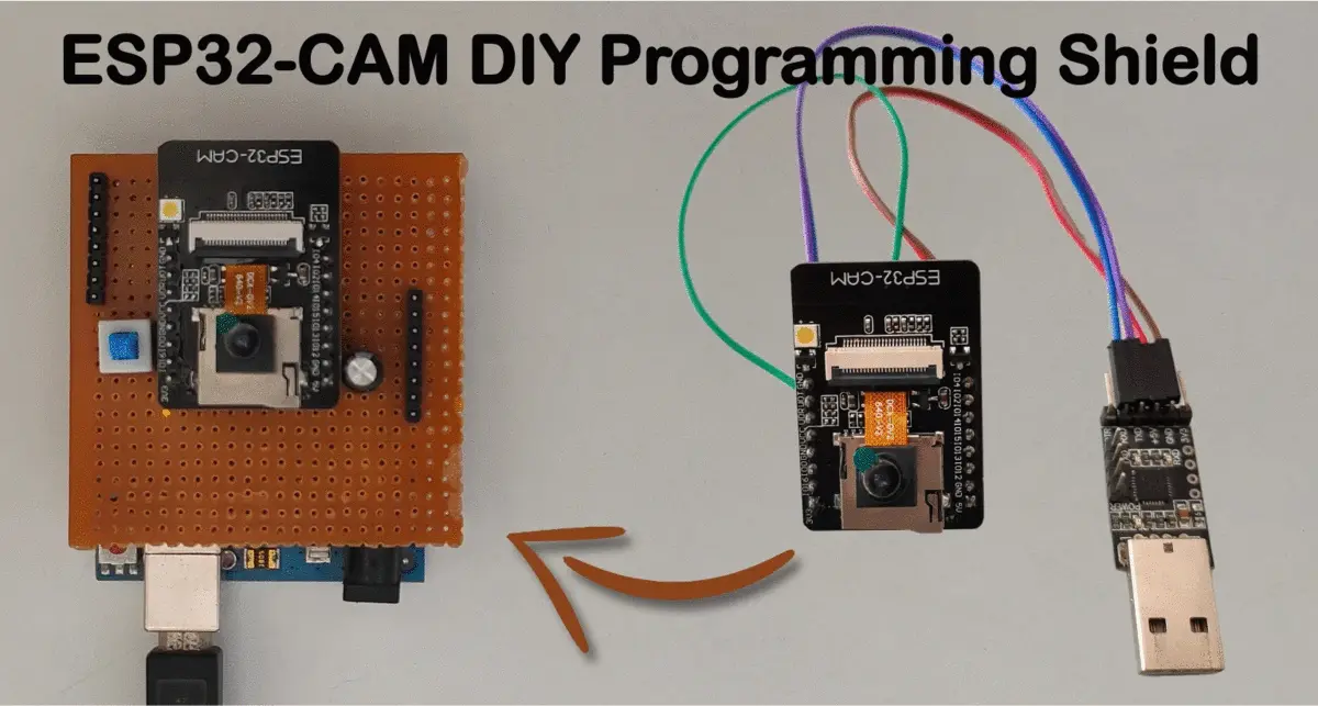
Due to this, it is tricky to program the ESP32-CAM board. Therefore in this tutorial, we will build a DIY shield that will help in programming ESP32-CAM quickly, and we will also discuss different ways for programming ESP32-CAM.
Parts Required:
- Prototyping PCB board.
- Male and female header pins.
- Switch.
- Soldering accessories.
- Any of the following Arduino-based development boards. Arduino UNO, Nano, ESP32.
We will use Arduino UNO in this tutorial.
Note:- We have tested Arduino UNO boards that have ATmega16U IC (for USB to UART conversion) will not work for this shield. It will sometimes work if we select board as ESP32 Wrover module.
Arduino UNO with standard USB to UART converter IC such as CH3401 will work perfectly.
In this tutorial, we have assumed that you have the essential skill of soldering. Additionally, you should be familiar with Arduino IDE. If you are not aware, then follow our easy to follow step by step guide on:
❑ Getting Familiar With Arduino IDE
How To Program ESP32-CAM?
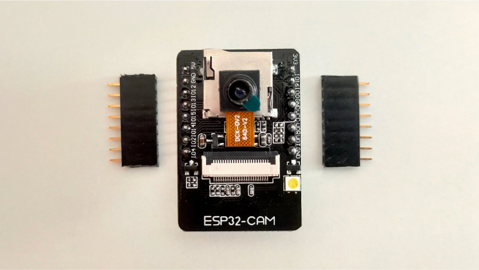
ESP32-CAM board has ESP32 module + Ov2640 camera module; therefore, the programming can be done similar to ESP32.
Before programming, ESP32 should be in programming mode (boot mode). We can do that by connecting GPIO 0 pin to GND(ground) on reset. After this, we can use any USB to UART converter for programming ESP32-CAM.
Just follow the connection given below to program your ESP32-CAM board using FTDI.
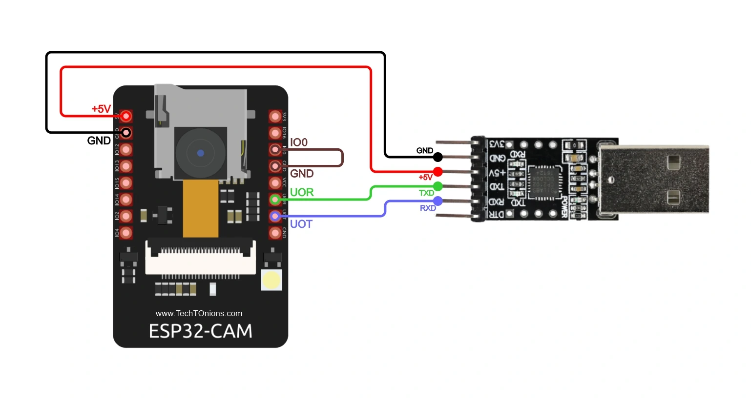
As seen, this method requires wiring every time, and additionally, we need to provide a 5v power to the ESP32-CAM board with jumper wires. Once programming is done, then to run your code, you need to remove the connection between GPIO 0 and GND; else, it will enter boot mode again.
If you think you want to avoid this wiring every time you program the ESP32-CAM board, stick around with us to build a DIY programming shield to make this process lot simpler.
Schematic Diagram
Here we have come up with different schematic diagrams for the shield used with various Arduino boards. We will call them programmer boards, and the ESP32-CAM will be our programming board.
If you have Arduino UNO without the ATmega16U chip on it, you can follow the schematic diagram below.
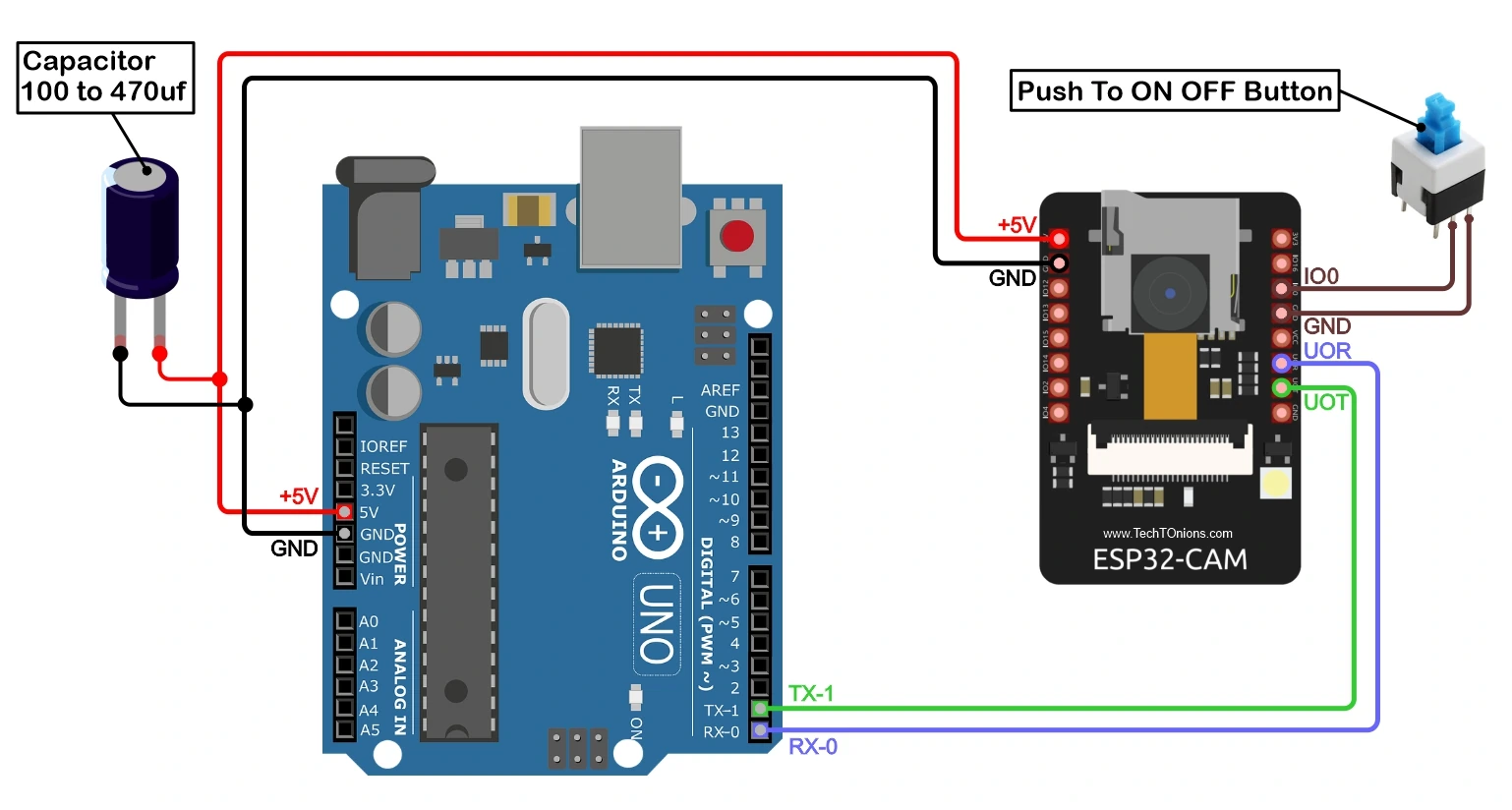
If you don’t have UNO, you can also follow the exact schematic for the Arduino NANO board. As both boards have the same pinouts.
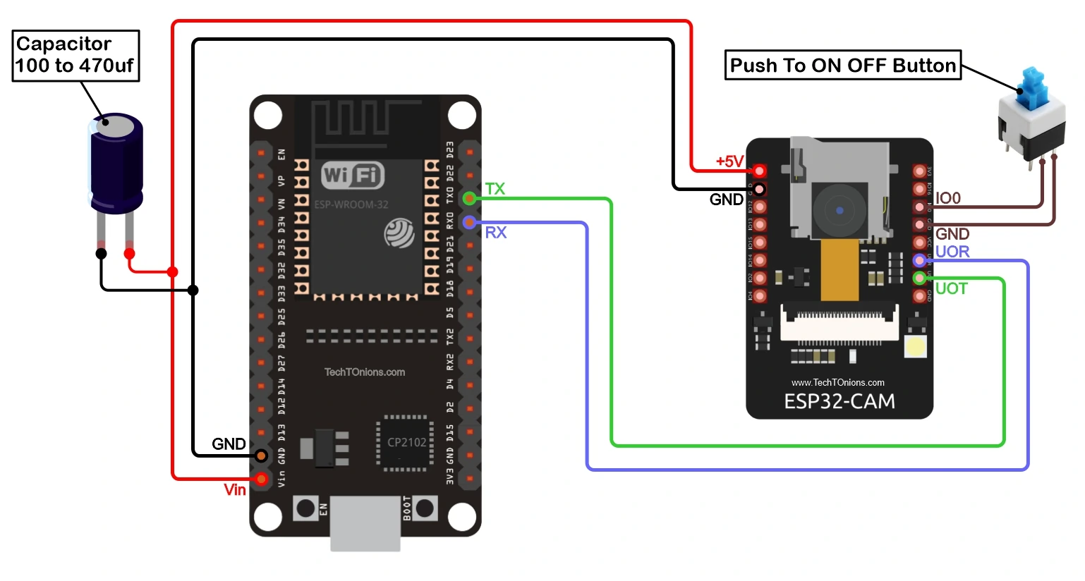
Finally, if you have an ESP32 development board, follow the below schematic diagram for developing the ESP32-CAM programmer shield.
Working Of ESP32-CAM Programmer Shield
As you have noticed, all the above schematics are pretty much the same, and just the programmer boards are different. Therefore the basic schematic will be standard for all boards.
As discussed earlier that for programming ESP32-CAM, it is necessary to put ESP32-CAM into serial bootloader mode. The only way to put ESP32 into serial bootloader mode is by providing logic 0 to GPIO 0 pin while ESP32 resets.
You can check more on such strapping pins of ESP32 at their Github repo.
For switching between bootloader mode and normal mode, we have placed a push to ON/OFF switch between GPIO 0 pin and GND pin of the ESP32-CAM board.
We have connected the Reset pin of the programmer board to the GND(ground) so that the controller of the programmer board will be in reset mode when we put the shield on them.
And the remaining we have connected programmer boards UART pins to the ESP32-CAM board so that the programmer board acts as USB to UART converter and will program the ESP32-CAM board. Additionally, we can provide power to the ESP32-CAM board from the programmer board’s USB port.
We have also added the small bulk capacitor of 100uF to provide a stable power supply to the ESP32-CAM board.
Let’s Start Building ESP32-CAM Programming Shield
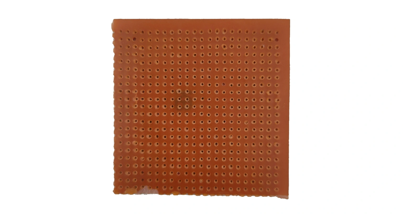
Starting with the prototyping PCB board, if you are using Arduino UNO like us, you can cut the PCB of the size of the UNO board. You can skip this step and cut it in the last if you cannot predict the PCB size required.
Now, we will cut the male header pins that will go inside the Arduino UNO board pins. You can place header pins near UNO pins to quickly count and cut the male header pins require.
You will need female header pins in case you are using Arduino Nano or ESP32 board.
If you want to learn more about different types of pin headers and their uses, check out our detailed guide on PCB pin headers.

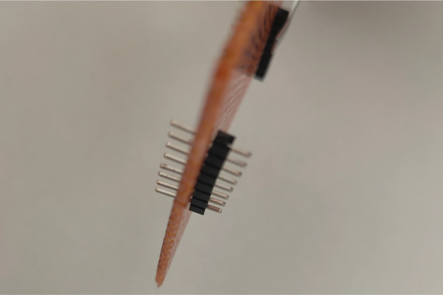
Insert the male header pins from the top side (No soldering side) of the prototyping PCB. It would be best if you matched the exact position of the header pins. Therefore it will be easily fit inside Arduino UNO female header pins.
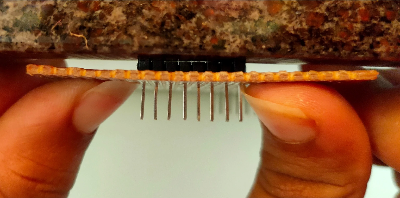
We will extend the length of the header pin from the bottom side. Therefore applying an even force from the top side so that only the plastic part of the header pin remains on the top side. Place your PCB near any solid block of wall or marble, as shown in the picture below.

Now we will apply a gentle force on PCB from the bottom side towards the wall until just the plastic part of the header pin remains on the top side of the PCB.
Note:- We need to do this because our prototype PCB was single-side solderable. That’s why it was not possible to solder it from the top side. You can also avoid it by using double side solderable prototype PCBs.
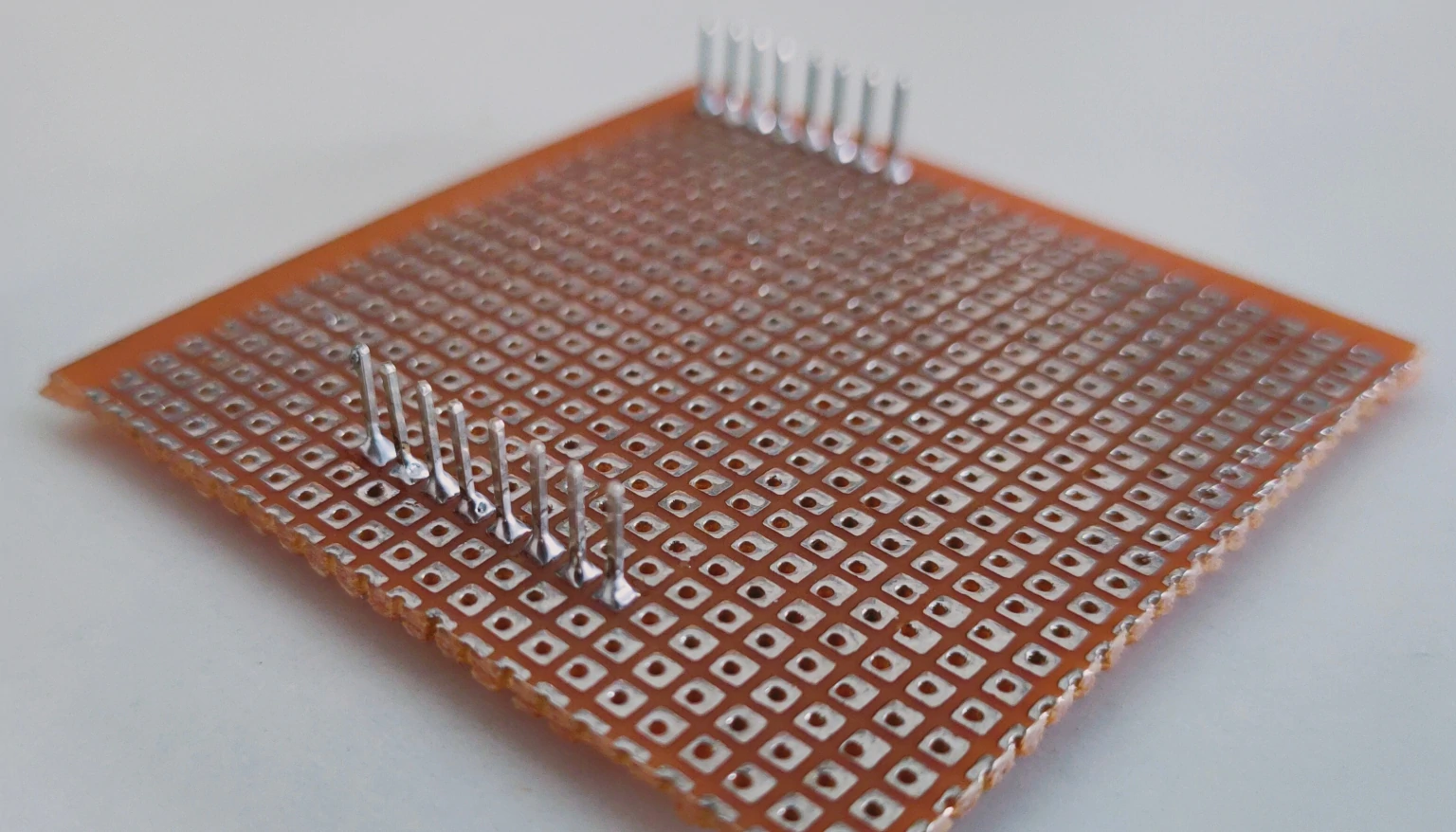
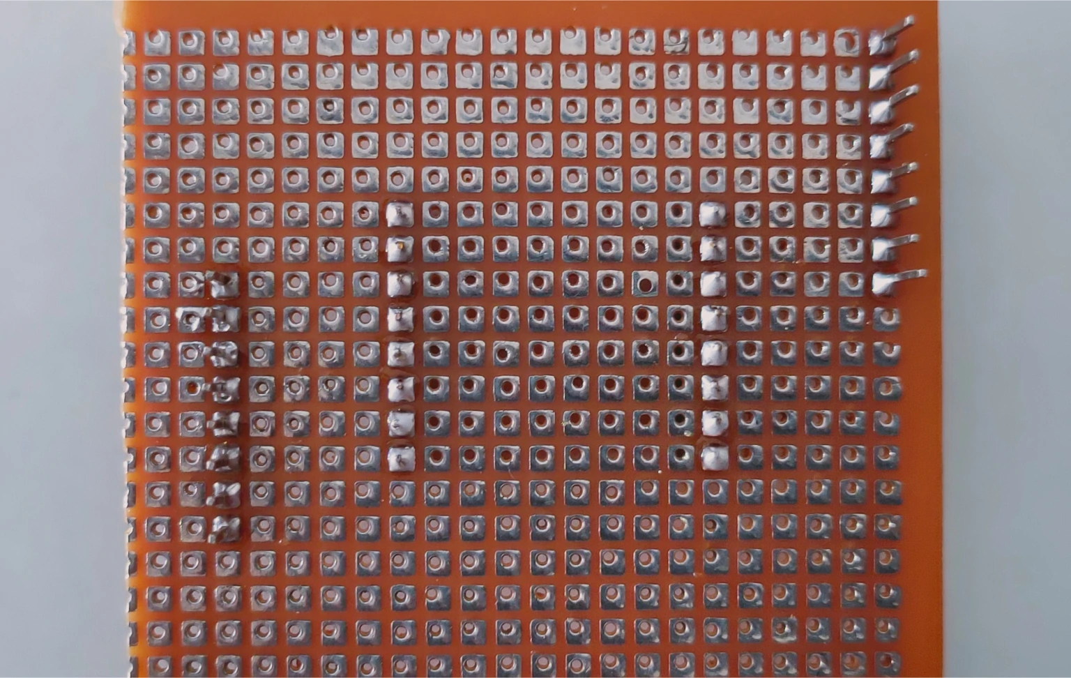
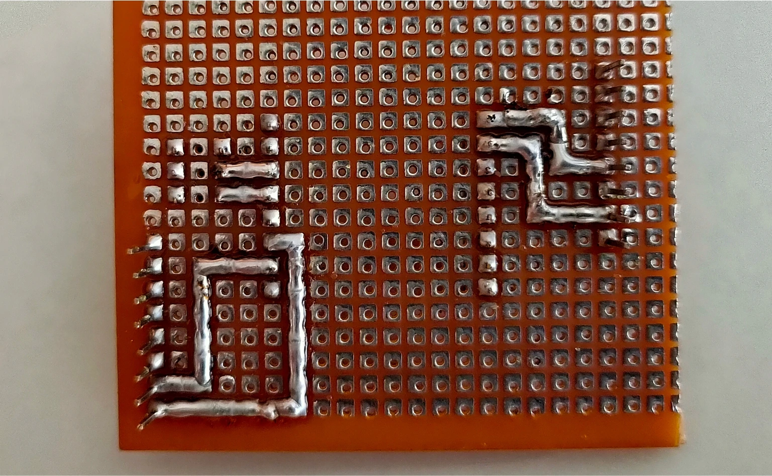
Now we will solder male header pins on the bottom side of the PCB to secure its position and connect with the PCB.

Our PCB will look like this after soldering all pins.
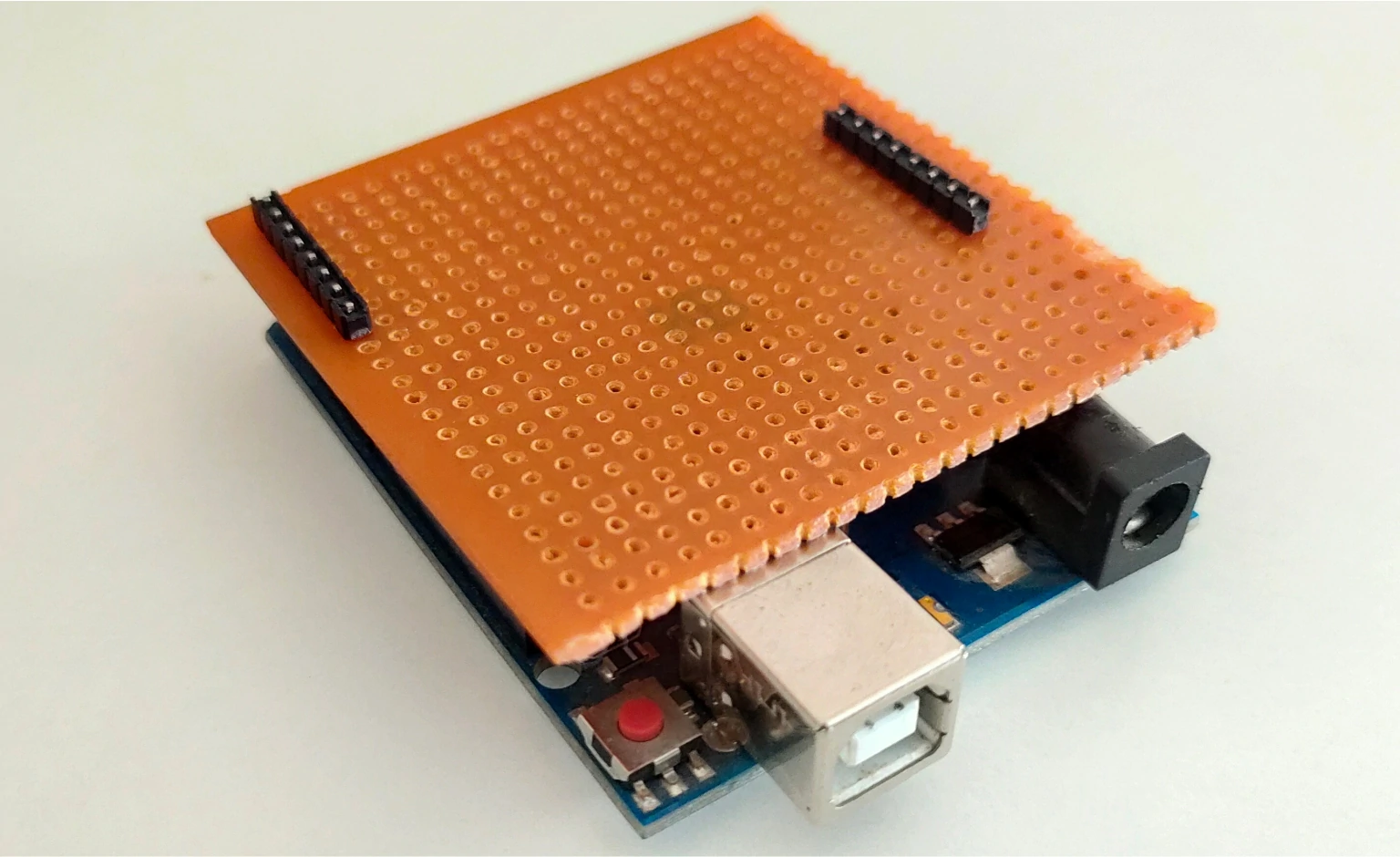
After soldering all Header pins, insert our shield to the Arduino UNO board to verify proper fitting.
Now, we will cut the two strips of female header pins as per the pins in our ESP32-CAM board.
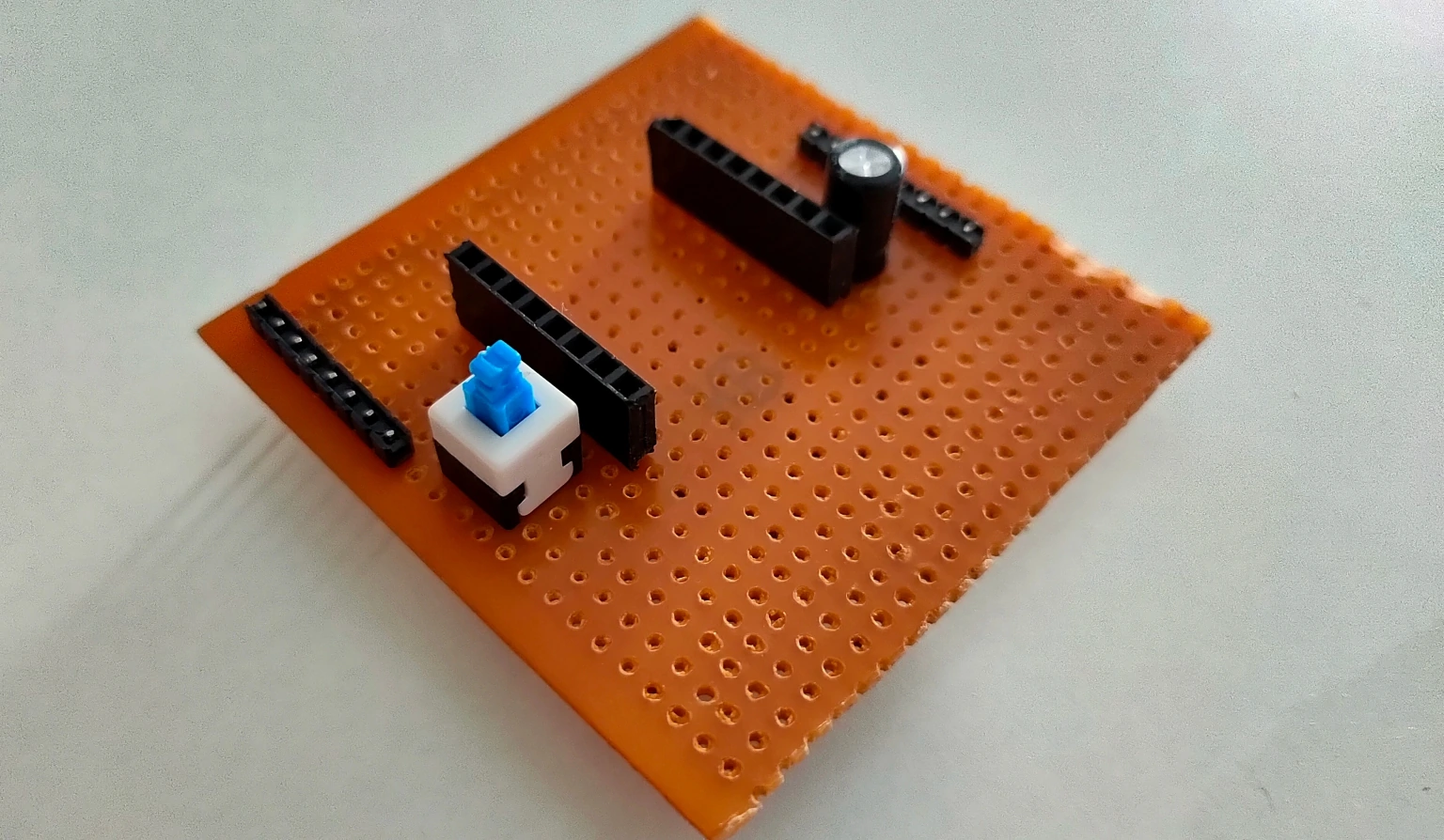
Insert female header pins on the middle portion of the PCB from the top side per spacing in the ESP32-CAM board. And solder all the female header pins.
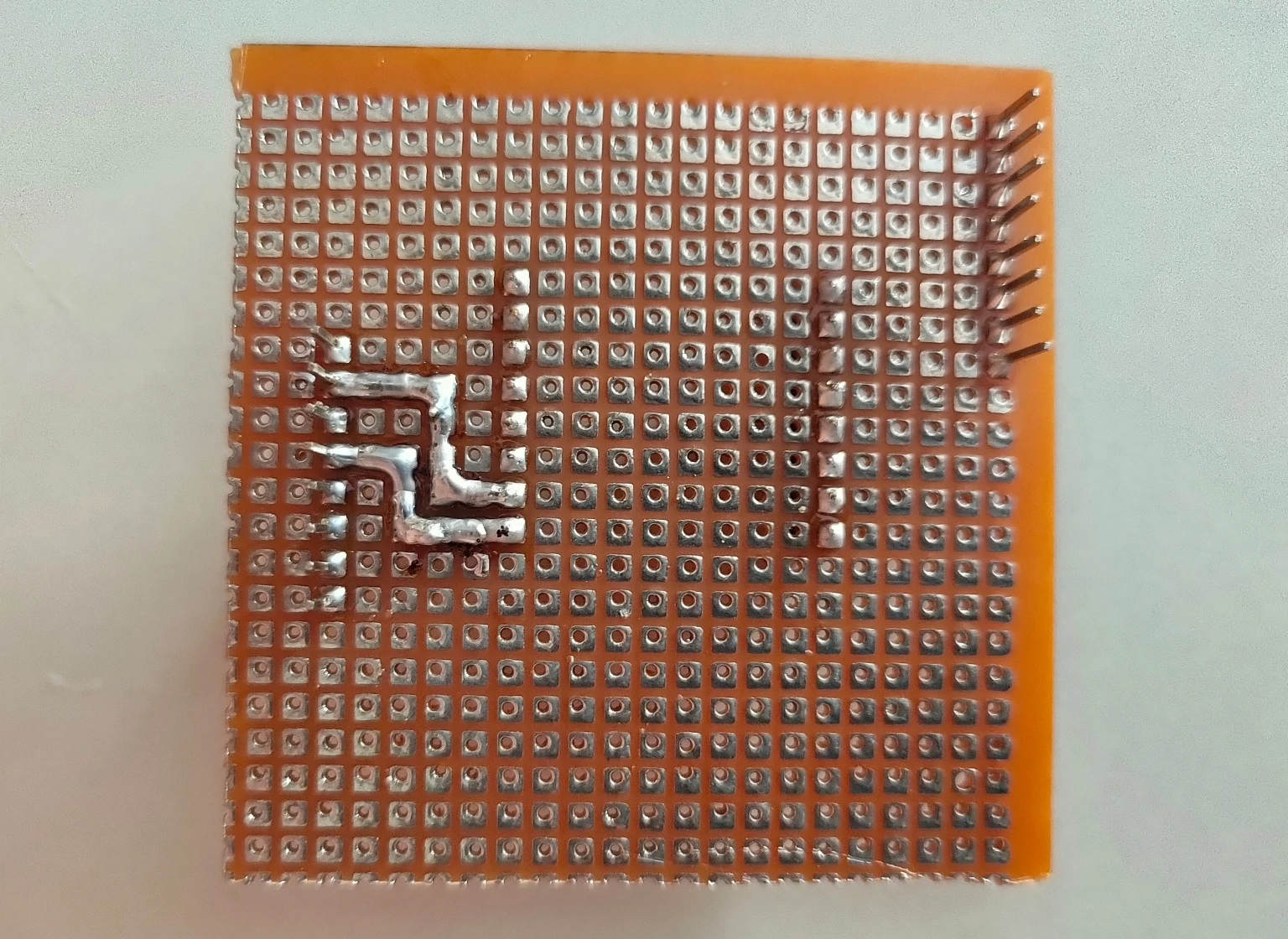
Our shield is almost ready now; we need to connect different pins as per the schematic diagram discussed before.
We will start by adding a 100uF capacitor between the 5v pin and GND.

Also, connecting UNO 5V and GND pins to ESP32-CAM 5V and GND pin.
Now we will solder the ON-OFF switch between GPIO 0 and GND pin of the ESP32-CAM board.
Soldering the reset pin of Arduino UNO board to GND pin.
Last we will solder the UART pins of the Arduino UNO board to the ESP32-CAM board. Additionally, soldering reset pin of Arduino UNO board to GND pin.
And our shield is ready for programming the ESP32-CAM board.
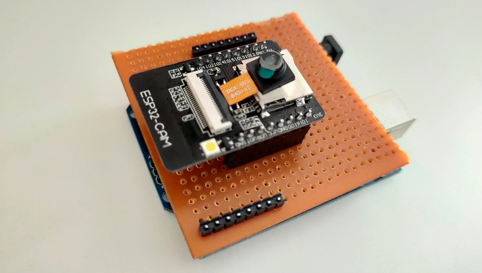
Programming ESP32-CAM With a DIY Shield
Connect the Arduino UNO board and ESP32-CAM board to our shield.
For programming ESP32-CAM, we need to install the ESP32 board package in Arduino IDE. If you have not installed the ESP32 board in Arduino IDE, then you can follow our easy tutorial on:
❑ Installing ESP32 In Arduino IDE
You will need to follow the below steps before programming the ESP32-CAM board every time.
- Unplug the USB cable connected to the Arduino UNO board if it’s connected. (This step is mandatory because there is no reset pin in the ESP32-CAM board, so we will reset it by powering it OFF).
- Press the switch to ON position to connect the GPIO 0 and GND pin of the ESP32-CAM board.
- Now plug in the USB cable to your computer and Arduino UNO board.
After this, you can follow the normal uploading process. Select the board that you are using in Arduino IDE. Go to Tools → Board.
For the ESP32-CAM board, we will select AI Tinker ESP32-CAM.
Now, select the appropriate COM port that Arduino UNO is connected to.
Copy-paste the below test code for ESP32-CAM in the Arduino IDE. This test code will only blink an onboard flash LED of the ESP32-CAM board at an interval of 1 second. The code is self-explanatory still if you want to learn more about blinking LED Arduino codes, then check our easy tutorial on:
❑ 6 Simple Ways To Blink Arduino LED
/*
  Code written by: Dharmik
  Basic LED blink code using Delay
  Code uses 924 bytes of program memory and Global variables use 9 bytes.
  Find more on www.TechTOnions.com
*/

#define LED 13 // Defining an LED variable as 13 because our LED is connected to pin 13
void setup() {
  pinMode(LED, OUTPUT); // Set LED pin as OUTPUT
}

void loop() {
  digitalWrite(LED, HIGH);    // turn LED ON by writing HIGH (Sending 5v to pin 13)
  delay(1000);                       // wait for a second
  digitalWrite(LED, LOW);     // turn LED OFF by writing LOW (Sending 0v to pin 13)
  delay(1000);                       // wait for a second
}
Now hit the upload button, and you will see the code will first compile, and then it will start uploading.
And if you have no errors in connections, you will see done uploading.
After just seeing it done uploading, the flash LED of ESP32-CAM will not start blinking. As ESP32 is still in boot mode, we need to put it in normal mode to see our code running. To do so, follow the below steps.
- Unplug the USB cable from your computer. (It will reset the ESP32-CAM board).
- Push the switch to OFF position to remove the connection between GPIO 0 and GND pin of ESP32-CAM board.
- Now plug the USB cable back into your computer.
You will now see your flash LED blinking on your ESP32-CAM board. That’s all now you have your DIY programming shield for ESP32-CAM is ready. Additionally, you can also provide power to your ESP32-CAM project from the DC jack of Arduino UNO.
Wrapping Up
We learned how to build a DIY programming shield to make the programming task simple. It’s even better if you have a dead Arduino board lying around and its com port is detected, then it’s better to convert them into a programming shield.
If you like this ESP32-CAM programming shield-making tutorial, consider subscribing to our weekly newsletters for more cool projects on the ESP32-CAM board.