Audio technology has gone a long way since the advent of the phonograph in the late 19th century. From the debut of magnetic tape in the 1930s to the 80s the advancement of digital audio continuously innovation and advancement. Here we are going to talk about Micro speakers.
The introduction of digital audio has been one of the most significant advances in audio technology. Unlike analog audio, which produces sound through physical vibrations, digital audio employs binary code to represent audio signals.
The Problem with Coil Speakers: Phase Distortion
Traditional coil speakers have limitations that affect sound quality, including phase distortion, and varying the timing of sound mid, and high frequencies. This can result in a muddled and unclear sound, particularly in the presence of multiple audio sources. Phase distortion in coil speakers highlights the need for innovative solutions like silicon speakers in audio technology.
xMEMS Labs‘ silicon-based speaker technology will replace century-old coil speakers. This allows for dependable mass manufacturing of solid-state speakers using semiconductor fabrication technology, resulting in better-fidelity, high-resolution audio.
xMEMS’s innovative solution to traditional audio technology lies in its development of silicon speakers. Traditional coil speakers can experience phase distortion and other audio quality issues. The silicon micro speakers are able to produce clearer and more accurate sound reproduction.
How Silicon Micro Speakers Work
Silicon micro speakers use a different mechanism to produce sound compared to traditional coil speakers. Instead of a coil, micro speakers use a thin frame made of silicon that is able to vibrate at high frequencies when current is applied. This vibration produces sound waves that are then amplified through a small cavity within the speaker housing.
xMEMS speakers use silicon membranes to achieve phase precision faster and more solidly than any coil speaker. Also, the $100,000 hi-fi speakers for mastering have a 7-degree phase shift (on a scale of zero to 360),
Silicon speakers, on the other hand, can reduce the phase shift to about 1 degree. There is no temporal delay in the way the sound is delivered.”
If you’re interested in learning more about xMEMS’s silicon micro speakers be sure to check this video
The Advantages of xMEMS’s Technology
Silicon speakers are also significantly smaller than traditional coil speakers, making them ideal for use in portable devices such as smartphones. Despite their small size, however, silicon micro speakers are able to produce high-quality sound that rivals larger speakers.
Silicon speakers have a significant advantage due to their small size, enabling them to function in various devices, including smartphones, wearables, and hearing aids. Moreover, they produce clearer and more accurate sound with reduced phase distortion than traditional coil speakers.
The Future of Sound Reproduction
xMEMS’s silicon micro speakers are set to have a major impact on the audio industry in the coming years. Silicon micro speakers are gaining popularity in various industries as they offer clearer and more accurate sound than traditional coil speakers.
Additionally, the compact and versatile nature of silicon speakers makes them suitable for use in diverse applications, such as smartphones and automotive systems.
Conclusion
In conclusion, xMEMS’s silicon speakers represent an exciting advancement in the field of audio technology. Using semiconductor manufacturing processes, silicon speakers offer advantages over traditional coil speakers in terms of precision, consistency, and sound quality.
Overall, the unique mechanism of silicon micro speakers makes them an innovative and promising solution for the future of sound reproduction.
Thank you for reading our blog! Don’t forget to check out our other informative posts by clicking on the links below.
Importance of thermal management in electronic devices
Effective thermal management is essential because electronic devices generate a significant amount of heat during their operation. This heat can cause damage to the device and even lead to its failure if not managed properly.
There are several reasons why thermal management is crucial in electronic devices. First, it helps to prevent overheating, which can cause damage to the internal components and affect the device’s performance. Overheating can also lead to the melting of wires and other parts, which can result in electrical shorts and other malfunctions.
Another reason why thermal management is important is that it can improve the reliability and lifespan of electronic devices. By maintaining a stable temperature, the device’s components are less likely to experience thermal stress, which can cause premature failure.
What is AirJet Solid State Cooling Chip
The AirJet Solid State Cooling Chip is a revolutionary cooling technology that provides an efficient and reliable thermal management solution for electronic devices. It utilizes air as a coolant, making it a highly cost-effective and energy-efficient alternative to traditional cooling methods.
Image: Frore Systems
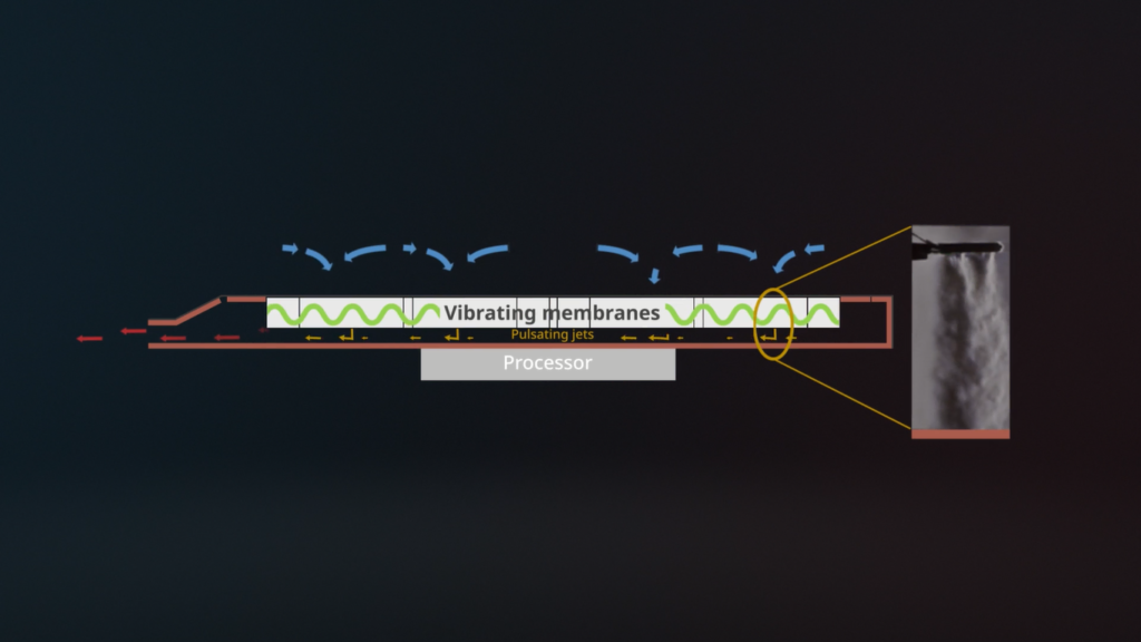
The AirJet is designed with a microchannel heat exchanger integrated into a silicon chip. This allows for rapid heat transfer away from the electronic device, keeping the chip at a stable temperature. The heat is then dissipated into the surrounding air, providing an effective and efficient cooling solution.
If you want to dive deeper into this topic, hit play on the video below for a more visual experience.
The pulsating jets of air remove heat from the heat spreader at the bottom of the AirJet with high efficiency. The flowing air reaches the same temperature as the heat spreader which is in contact with the processor. Hot air exits to the side via an integrated spout. Moreover, AirJet technology offers a compact and lightweight design, making it an ideal solution for electronic devices with limited space.
Advantages of using AirJet for thermal management
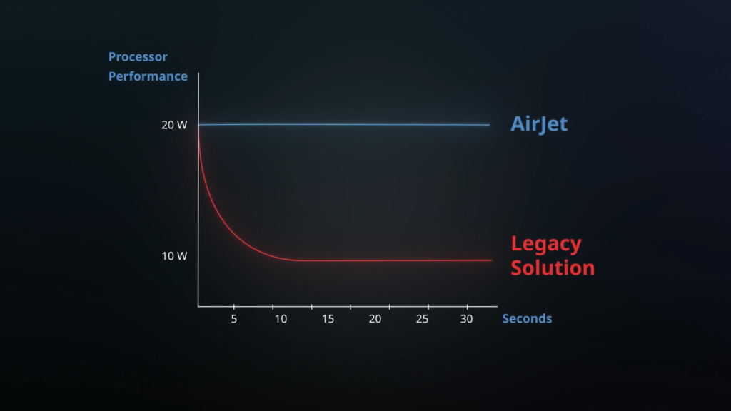
One of the key advantages of the AirJet Solid State Cooling Chip is its energy efficiency. Compared to typical cooling technologies, such as fans and pumps.
The AirJet chip utilizes much less energy, resulting in decreased energy consumption and cost savings. This makes it a great choice for electrical equipment that demands efficient and cost-effective cooling.
Another key advantage of the AirJet is that it does not rely on mechanical parts, it requires minimal maintenance. This makes it a reliable solution for electronic devices that require high levels of uptime and dependability.
It can be easily integrated into a wide range of devices, including mobile phones, laptops, tablets, and other portable devices.
Image: Frore Systems
For More Info about how AirJet is more beneficial than legacy Solutions check the Frore System website.
How does AirJet Solid State Cooling Chip work
Desktops use different of methods to cool chips, including radiators and coolers, massive fans, and even water cooling via many hoses. However, a desktop case provides enough interior space to make those alternatives feasible. Because laptops and tablets have little storage space, these options are significantly less viable. That’s what makes Frore’s AirJet so fascinating.
These solid-state coolers have the potential to increase heat dissipation capabilities when stacked side by side. A prime example would be 5 AirJet Pro units, which have the ability to cool a 50W CPU. It’s remarkable how effective they are! With the capability to blow air up to 200 km/h, the cooling power is truly impressive.
Frore Systems developed two chips, the AirJet Mini and Pro, that will be attached to a laptop’s processor in place of a heat pipe or fan. According to business executives, both chips practically silently cool the laptop’s CPU, providing more air pressure but also less disruptive noise than a traditional fan.
Image: Frore Systems
Frore anticipates that their AirJet chips will significantly reduce internal heat within a laptop, allowing the machine to function longer in a higher-power mode. That would be around 1.5 times the present performance of a laptop.
The pulsating jets of air remove heat from the heat spreader at the bottom of the AirJet with high efficiency. The flowing air reaches the same temperature as the heat spreader which is in contact with the processor. The heat is then dissipated into the surrounding air, providing an effective and energy-efficient cooling solution.
After reviewing the benefits of AirJet Solid State Cooling Chip for thermal management, it is clear that this technology is a highly efficient and reliable solution for regulating the temperature of electronic devices.
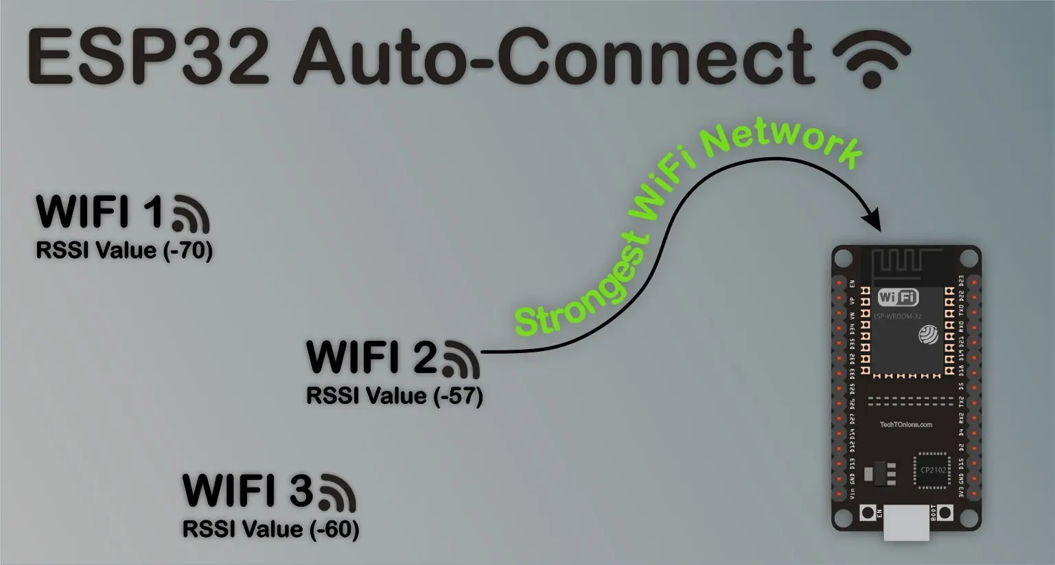
Do you know we can store multiple WiFi credentials in ESP32? Not just storing ESP32 can automatically connect to the strongest WiFi network among them.
Project Overview
IoT is all about internet connectivity, and until now, we only depended on one WiFi credential stored in our ESP32. But depending on a single WiFi network is not sufficient for reliable operation.
In this guide, we will discuss how we can store multiple WiFi credentials in our ESP32 code. And among all the WiFi networks, ESP32 will automatically connect to the best network.
This way, we can ensure the best internet connectivity to our ESP32 based IoT projects.
Parts Needed
For this tutorial, we will use the following parts:
ESP32 Development Board
Breadboard
Prerequisites
We will be using Arduino IDE for programming ESP32. If you are not familiar with Arduino IDE, then check out our guide on
/*
Date: 24-09-21
Code written by: Dharmik
This sketch trys to Connect to the best WiFi network based on a given list
Find more on www.TechTOnions.com
*/
#include <WiFi.h>
#include <WiFiMulti.h>
WiFiMulti wifiMulti;
#define WiFi_timeout 10000 // 10sec Wifi connection timeout
const char* ssid0 = "TechTOnions";
const char* pass0 = "Dtirth123";
const char* ssid1 = "aaaaaaa";
const char* pass1 = "12345678";
const char* ssid2 = "Your SSID 2";
const char* pass2 = "Your Password 2";
const char* ssid3 = "Your SSID 3";
const char* pass3 = "Your Password 3";
void setup()
{
Serial.begin(115200);
delay(100);
//Adding all WiFi credential to WiFi multi class
wifiMulti.addAP(ssid0, pass0);
wifiMulti.addAP(ssid1, pass1);
wifiMulti.addAP(ssid2, pass2);
wifiMulti.addAP(ssid3, pass3);
Serial.println("Connecting Wifi...");
//Connecting to the strongest WiFi connection
if (wifiMulti.run(WiFi_timeout) == WL_CONNECTED)
{
Serial.println("");
Serial.println("WiFi connected");
Serial.println("IP address: ");
Serial.println(WiFi.localIP()); //print IP of the connected WiFi network
}
else // if not WiFi not connected
{
Serial.println("WiFi not Connected");
}
}
void loop()
{
// if WiFi is not connected try again to connect with default timeout of 5sec
if (wifiMulti.run() != WL_CONNECTED) {
Serial.println("WiFi not connected!");
delay(1000);
}
}
How Code Works
First, we need to initialize the required libraries. We will need WiFi.h and WiFiMulti.h.Both of these libraries are preinstalled with the ESP32 package.
#include <WiFi.h>
#include <WiFiMulti.h>
Now we will initialize wifiMulti as a new WiFiMulti class.
WiFiMulti wifiMulti;
We will define WiFi_timeoutWiFi_timeout; this will set the max timeout for connecting to the WiFi network. We have set it to 10000milli seconds (10sec). You can reduce or increase it if needed.
For this guide, we have defined four different WiFi credentials you may have more or less in your case. Therefore we have defined all of them as const char* and named them as ssid0, pass0 until ssid3, pass3. You can use different naming if you like.
Note: Any of your SSID and Password lengths should not be greater than 31 and 64.
setup()
First, we will initialize the serial communication so we can see data in the Serial monitor. We have used a baud rate of 115200. And, adding little delay.
Serial.begin(115200);
delay(100);
Now, we will use the addAP function from library WiFiMulti to add all the WiFi credentials in the following manner.
We have four different WiFi credentials; therefore, we need to use this function four times and pass it with varying WiFi credentials. If you have more or less WiFi networks, you can use this function accordingly.
Finally, we need to use the run function with the previous WiFi_timeoutWiFi_timeout defined. This function will take care of choosing the best WiFi network out of all. This function will check all the available networks with strengths and will choose the strongest among them.
if (wifiMulti.run(WiFi_timeout) == WL_CONNECTED)
{
Serial.println("");
Serial.println("WiFi connected");
Serial.println("IP address: ");
Serial.println(WiFi.localIP()); //print IP of the connected WiFi network
}
else // if not WiFi not connected
{
Serial.println("WiFi not Connected");
}
If this function connects to WiFi within the specified timeout, we will print the IP address of the connected WiFi network. And if not connected to any WiFi, we will serial print “WiFi not connected” in the serial monitor.
loop()
In the loop function, we will only check every time that the WiFi is connected or not. If it is not connected, it will try to connect WiFi with the default timeout of 5sec.
if (wifiMulti.run() != WL_CONNECTED) {
Serial.println("WiFi not connected!");
delay(1000);
}
That’s all we need to do to enable this cool feature of the ESP32. You can skip the last part of this guide. But, if you want to know what exactly this library is doing, stick around with us.
Let’s Dig Deeper
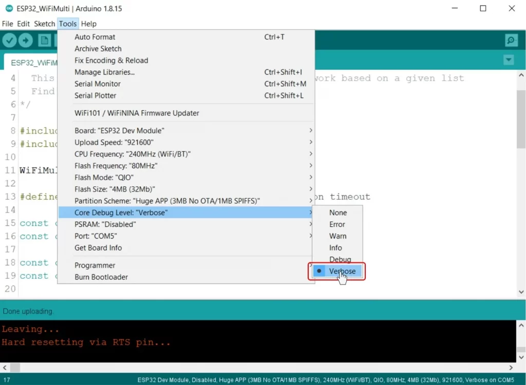
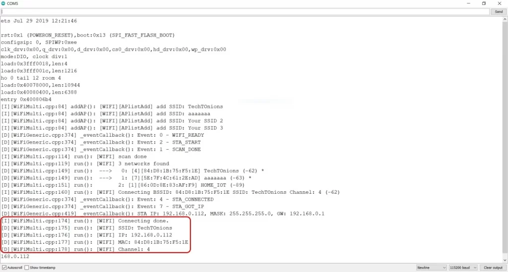
Let us understand what exactly this library is doing in the background. To do so, we will be enabling the verbose output.
To do so, go to Tools > Core Debug Level > Verbose
And now upload the code.
This way, the library will print all the additional data in the background to the serial monitor. And you will observe ESP32 will print lots of data in the Serial terminal.
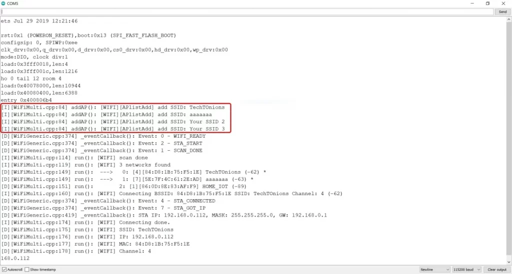
The first thing that we will observe, the library has added all four SSID that we have passed with the addAP function.
Next, the library has scanned all the available WiFi networks that are in range. And as we can see that three networks are found.
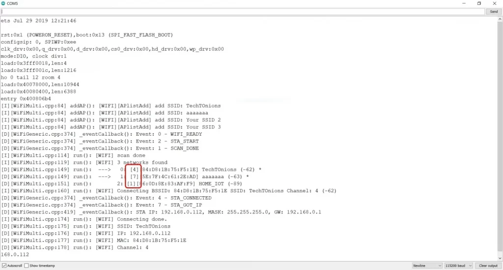
The square brackets represent the WiFi channel of that particular SSID.
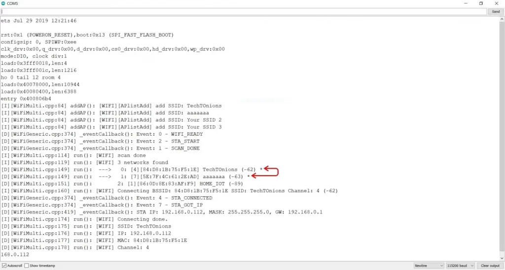
We can see the first two SSID are in our code. That’s why they are marked as *.
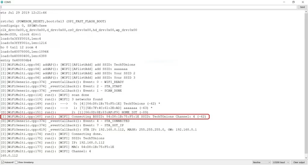
And in a bracket, it is the RSSI value of all available WiFi networks. We know that the RSSI value closest to 0 has the strongest network strength. In our case, it is the SSID0 named as TechTOnions, which is -62, the strongest among the two available networks.
Therefore it is connected with TechTOnions and will display the IP and MAC address of the WiFi network.
Wrapping Up
In this tutorial, you’ve learned how easily we can store multiple WiFi credentials to our ESP32 project and let ESP32 itself decide which network is best to use. This way, our ESP32 based project will always connect to the most robust available WiFi network based on the RSSI value.
We hope you learned something new today and will try it out. If you like our tutorial and want more such ESP32 based tutorials, consider subscribing to our weekly newsletter. And don’t forget to leave us a comment after trying out this project with your ESP32.
This tutorial will cover how to use Signal bot API to send notifications and images from ESP32 to your signal account. At the end of this tutorial, we will use two buttons connected to ESP32.
The first button will send a message showing the total Button press count to your signal app. Another button press will send an image to your Signal app.
It’s a simple project using API for interacting with the Signal app. You can use it in your IoT or any Home automation project based on ESP.
Watch the Video Tutorial
Introduction to Signal app
The Signal is a cross-platform centralized encrypted messaging service. It uses the internet to send a message such as an image, voice, video, etc. It is similar to a different messaging app like WhatsApp, but it focuses more on user privacy to enhance the overall user experience. Signal software allows us to use a bot to interact with them.
A bot is third-party software that runs on the signal app. You can interact with the bot, and the bot will interact with the signal app using a different bot API; it will act as a middle person. We can control our bot by sensing HTTPS requests to the bot API.
ESP32 will monitor the button press, and based on that, it will interact with the bot API, and it will send a message or an image to your Signal account.
Setting up a Signal bot
The first step will be to download the Signal app from google play or the app store. Skip if you have are already using a signal app.
The bot that we will use in this project is known as Callmebot. Steps to add bot to your Signal app are as followed-
Add this exact phone number +34 603 21 25 97 into your Phone Contacts. (you can name it as you like). Therefore we have saved this number as “Signal Bot.”
From the Signal app, you have to send this exact message “I allow callmebot to send me messages” to the same bot number you saved in step 1.
The bot will immediately reply with your API key. Copy that API key. We will use that key in our ESP32 code.
After these three simple steps completion out Signal Bot is ready to interact with our ESP32, it’s that simple.
Preparing Arduino IDE
To program ESP32 using Arduino IDE, we have to install the ESP32 board to Arduino IDE first. Follow our guide on.
We will require an EasyButton.h library from evert-arias for the final example. This library takes care of button debouncing. For installing the library, follow these steps.
Click here to download the latest release of EasyButton.h.
Go inside Sketch > Include Library > Add .Zip Library.
Browse the downloaded zip file from step 1.
For more details, you can check out EasyButton.h library Github Repository.
Parts Required
For this project, you will require the following parts.
ESP32 board or ESP8266
Additional requirement for a final example
Breadboard
2x button
jumper or hookup wires.
Understanding Signal message sending API
Below is the API format to send a text message to the Signal app. Therefore we can use the HTTPS post method to send a text message to the Signal app using ESP32.
[phone_number]: Your Phone number, including the country code. Ex. +91 756 712 123
[apiKey ]: Your API key that you received in Setting up a Signal bot step 3.
[message]: Text message you want to send ( all space ‘ ‘ need to be converter to ‘+’)
Example:
https://api.callmebot.com/signal/send.php?phone=+91756712123&apikey=598890&text=Hello+from+ESP32 Calling the above URL in any browser search bar, you will get “Hello from ESP32” as a message in the Signal app if your phone number and API key are correct.
Sending Message to Signal Appwith ESP32
The following code will send your message once on startup to the Signal bot using its API. Therefore you will receive one message to your Signal app when ESP32 powers ON or ESP32 reset.
Following changes are required to use this code with your Signal app-
Add your Wi-Fi credentials to the ssid and password variable.
Add your API key to you to apiKey variable. (Same API key that you received by bot)
Add your registered Signal app mobile number with country code to the phone_number variable.
/*
Date: 07-05-21
Code written by: Dharmik
ESP32 sending a message to Signal messenger
Find more on www.TechTOnions.com
*/
#include <WiFi.h> //Including wifi.h library it will take care of all wifi related task
#include <HTTPClient.h> //Including HTTPClient.h library to use all api
const char* ssid = "Replace me with your SSID"; //Add your WiFi ssid
const char* password = "Replace me with your PASSWORD"; //Add your WiFi password
String apiKey = "222222"; //Add your Token number that bot has sent you on signal messenger
String phone_number = "+917561123123"; //Add your signal app registered phone number (same number that bot send you in url)
String url; //url String will be used to store the final generated URL
void setup()
{
Serial.begin(115200);
WiFi.begin(ssid, password); // Try to connect with the given SSID and PSS
Serial.println("Connecting to WiFi");
while (WiFi.status() != WL_CONNECTED) { // Wait until WiFi is connected
delay(500);
Serial.print(".");
}
Serial.println();
Serial.println("Connected to the WiFi network"); // Print wifi connect message
// use message_to_signal function to send your own message
message_to_signal("Hello from TechTOnions."); // you send your own message just change "hello from TechTOnions" to your message.
}
void loop()
{
//loop will do nothing for this example
}
void message_to_signal(String message) // user define function to send meassage to Signal app
{
//adding all number, your api key, your message into one complete url
url = "https://api.callmebot.com/signal/send.php?phone=" + phone_number + "&apikey=" + apiKey + "&text=" + urlencode(message);
postData(); // calling postData to run the above-generated url once so that you will receive a message.
}
void postData() //userDefine function used to call api(POST data)
{
int httpCode; // variable used to get the responce http code after calling api
HTTPClient http; // Declare object of class HTTPClient
http.begin(url); // begin the HTTPClient object with generated url
httpCode = http.POST(url); // Finaly Post the URL with this function and it will store the http code
if (httpCode == 200) // Check if the responce http code is 200
{
Serial.println("Sent ok."); // print message sent ok message
}
else // if response HTTP code is not 200 it means there is some error.
{
Serial.println("Error."); // print error message.
}
http.end(); // After calling API end the HTTP client object.
}
String urlencode(String str) // Function used for encoding the url
{
String encodedString="";
char c;
char code0;
char code1;
char code2;
for (int i =0; i < str.length(); i++){
c=str.charAt(i);
if (c == ' '){
encodedString+= '+';
} else if (isalnum(c)){
encodedString+=c;
} else{
code1=(c & 0xf)+'0';
if ((c & 0xf) >9){
code1=(c & 0xf) - 10 + 'A';
}
c=(c>>4)&0xf;
code0=c+'0';
if (c > 9){
code0=c - 10 + 'A';
}
code2='\0';
encodedString+='%';
encodedString+=code0;
encodedString+=code1;
//encodedString+=code2;
}
yield();
}
return encodedString;
}
You will see this message in your Signal app “Hello from TechTOnions.” once uploading is completed and ESP32 gets a proper Internet connection. Additionally, you will see sent ok message printed on the serial monitor.
How code works
The first step will be to include a required library for the example.
WiFi.h library will take care of all wifi-related tasks like connecting to your Wi-Fi.
HTTPClient.h library used to post the API with HTTP requests.
#include <WiFi.h> //Including wifi.h library it will take care of all wifi related task
#include <HTTPClient.h> //Including HTTPClient.h library to use all api
Network Credentials
Insert your Wi-Fi network credentials. So that ESP32 can connect to your Wi-Fi network for Internet connection.
const char* ssid = "Replace me with your SSID"; //Add your WiFi ssid
const char* password = "Replace me with your PASSWORD"; //Add your WiFi password
Signal Bot Credentials
Insert the API key that you received in Setting up a Signal bot step 3. Additionally, add your Phone number with the country code that your signal app is registered.
String apiKey = "222222"; //Add your Token number that bot has sent you on signal messenger
String phone_number = "+917561123123"; //Add your signal app registered phone number (same number that bot send you in URL)
setup()
First, we will initialize the serial communication so we can see data in the Serial monitor.
Serial.begin(115200);
Init the Wi-Fi
Initialize the Wi-Fi So that it can connect to your Wi-Fi network.
Note: If your Wi-Fi credentials are wrong, then ESP will be stuck in the infinite while loop.
WiFi.begin(ssid, password); // Try to connect with the given SSID and PSS
Serial.println("Connecting to WiFi");
while (WiFi.status() != WL_CONNECTED) { // Wait until WiFi is connected
delay(500);
Serial.print(".");
}
Serial.println();
Serial.println("Connected to the WiFi network"); // Print wifi connect message
Finally, we will send a message to the Signal app by calling our user-defined function named message_to_signal. You can change the message that you want to send.
It will send “hello from TechTOnions.” if you do not modify the existing message.
message_to_signal (String message)
message_to_signal is our user-defined function that will send messages to Signal App.
Inside this function, it will generate the final url String used for HTTP GET request. The final url will consist of an API url with your phone number, API key, and your message in encoded form.
To encode the message, we will pass the message to the urlencode function.
We are finally calling the postData function to send the message.
void message_to_signal(String message) // user define function to send meassage to Signal app
{
//adding all number, your api key, your message into one complete url
url = "https://api.callmebot.com/signal/send.php?phone=" + phone_number + "&apikey=" + apiKey + "&text=" + urlencode(message);
postData(); // calling postData to run the above-generated url once so that you will receive a message.
}
postData()
postData is another user-defined function used to send the URL using the HTTP GET method.
Initialize the new http object with HTTPClient. And begin the new http object with the final url build.
HTTPClient http; // Declare object of class HTTPClient
http.begin(url); // begin the HTTPClient object with generated url
Post the url by calling this POST function and save the HTTP response code in the httpCode variable.
httpCode = http.POST(url); // Finaly Post the URL with this function and it will store the http code
Now we will check the httpCode that we received, and if it is 200, POST was successful. Therefore printing “Sent ok.” in Serial monitor. If not 200, then printing “Error.” as POST is not successful.
Finally, we will end the http object by calling the end function.
if (httpCode == 200) // Check if the responce http code is 200
{
Serial.println("Sent ok."); // print message sent ok message
}
else // if response HTTP code is not 200 it means there is some error.
{
Serial.println("Error."); // print error message.
}
http.end(); // After calling API end the HTTP client object.
urlencode(String str)
This function is used to encode the standard URL because it is necessary to encode sending messages or URL when using HTTP GET request.
String urlencode(String str) // Function used for encoding the url
{
String encodedString="";
char c;
char code0;
char code1;
char code2;
for (int i =0; i < str.length(); i++){
c=str.charAt(i);
if (c == ' '){
encodedString+= '+';
} else if (isalnum(c)){
encodedString+=c;
} else{
code1=(c & 0xf)+'0';
if ((c & 0xf) >9){
code1=(c & 0xf) - 10 + 'A';
}
c=(c>>4)&0xf;
code0=c+'0';
if (c > 9){
code0=c - 10 + 'A';
}
code2='\0';
encodedString+='%';
encodedString+=code0;
encodedString+=code1;
//encodedString+=code2;
}
yield();
}
return encodedString;
}
For example,
If you want to send “Hello World“, it should be encoded as “Hello+World“.
And if you want to send the URL “https://www.techtonions.com/“, then the encoded URL will be like “https%3A%2F%2Fwww.techtonions.com%2F“.
loop()
For this example, the loop() function will be empty. You can add your code in the loop function. You can also send multiple messages by calling the message_to_signal again inside the loop.
Note:- Calling the message_to_signal function inside the loop without delay can crash the bot, so have some delay if you do so.
Understanding Signal Image sending API
Image sending API is similar to message sending API. Hence you can send any Image to the Signal app by HTTP get method by ESP32.
[phone_number]: Your Phone number, including the country code. Ex. +91 756 712 123
[apiKey ]: Your API key that you received in Setting up a Signal bot step 3.
[image_url]: put any image encoded URL you like here (Only works for .jpg .gif .png)
Sending Image to Signal App with ESP32
In this example, we will send the Image to the Signal app from ESP32. For this example, we are sending the TechTOnions logo. Therefore you will receive our logo to your Signal app when ESP32 powers ON or ESP32 reset.
Following changes are required to use this code with your Signal app-
Add your Wi-Fi credentials to the ssid and password variable.
Add your API key to you to apiKey variable. (Same API key that you received by bot)
Add your registered Signal app mobile number with country code to the phone_number variable.
/*
Date: 07-05-21
Code written by: Dharmik
ESP32 sending image to Signal messenger
Find more on www.TechTOnions.com
*/
#include <WiFi.h> //Including wifi.h library it will take care of all wifi related task
#include <HTTPClient.h> //Including HTTPClient.h library to use all api
const char* ssid = "Replace me with your SSID"; //Add your WiFi ssid
const char* password = "Replace me with your PASSWORD"; //Add your WiFi password
String apiKey = "222222"; //Add your Token number that bot has sent you on signal messenger
String phone_number = "+917561123123"; //Add your signal app registered phone number with country code (the same number that bot send you in url)
String url; //url String will be used to store the final generated URL
void setup() {
Serial.begin(115200);
WiFi.begin(ssid, password); // Try to connect with the given SSID and PSS
Serial.println("Connecting to WiFi");
while (WiFi.status() != WL_CONNECTED) { // Wait until WiFi is connected
delay(500);
Serial.print(".");
}
Serial.println();
Serial.println("Connected to the WiFi network"); // Print wifi connect message
//image_to_signal function will send your image to Signal app
//Just you have to add your image url
//it only works for .jpg .gif .png // not working with .webp image format
image_to_signal("https://www.techtonions.com/wp-content/uploads/2021/05/New-Profile-picture-logo-big-250x250-1.jpg");
}
void loop()
{
//loop will do nothing for this example
}
void image_to_signal(String img_url) //user define function to send image to Signal App
{
//adding all number, your api key, your image url into one complete url
url = "https://api.callmebot.com/signal/send.php?phone="+ phone_number + "&apikey=" + apiKey + "&image=" + urlencode(img_url);
postData(); // caling postData to run the above generated url once so that you will receive image.
}
void postData() //userDefine function used to call api(POST data)
{
int httpCode; // variable used to get the responce http code after calling api
HTTPClient http; // Declare object of class HTTPClient
http.begin(url); // begin the HTTPClient object with generated url
httpCode = http.POST(url); // Finaly Post the URL with this function and it will store the http code
if (httpCode == 200) // Check if the responce http code is 200
{
Serial.println("Sent ok."); // print message sent ok message
}
else // if response HTTP code is not 200 it means there is some error.
{
Serial.println("Error."); // print error message.
}
http.end(); // After calling API end the HTTP client object.
}
String urlencode(String str) // Function used for encoding the url
{
String encodedString="";
char c;
char code0;
char code1;
char code2;
for (int i =0; i < str.length(); i++){
c=str.charAt(i);
if (c == ' '){
encodedString+= '+';
} else if (isalnum(c)){
encodedString+=c;
} else{
code1=(c & 0xf)+'0';
if ((c & 0xf) >9){
code1=(c & 0xf) - 10 + 'A';
}
c=(c>>4)&0xf;
code0=c+'0';
if (c > 9){
code0=c - 10 + 'A';
}
code2='\0';
encodedString+='%';
encodedString+=code0;
encodedString+=code1;
//encodedString+=code2;
}
yield();
}
return encodedString;
}
How code works
The code is all similar to the message sending code. We will require the same library for this code also. You’ll need to add your Wi-Fi credentials, API key, and Phone number as described in the message send method.
#include <WiFi.h> //Including wifi.h library it will take care of all wifi related task
#include <HTTPClient.h> //Including HTTPClient.h library to use all api
const char* ssid = "Replace me with your SSID"; //Add your WiFi ssid
const char* password = "Replace me with your PASSWORD"; //Add your WiFi password
String apiKey = "222222"; //Add your Token number that bot has sent you on signal messenger
String phone_number = "+917561123123"; //Add your signal app registered phone number with country code (the same number that bot send you in url)
setup()
Inside setup function serial begin and Wi-Fi init logic will be same, but we will not use the message_to_signal function; instead, we will use another user-defined function for the Image sending name as image_to_signal.
You need to send an image URL with this function, and it will send your Image to the Signal app.
//image_to_signal function will send your image to Signal app
//Just you have to add your image url
//it only works for .jpg .gif .png // not working with .webp image format
image_to_signal("https://www.techtonions.com/wp-content/uploads/2021/05/New-Profile-picture-logo-big-250x250-1.jpg");
image_to_signal(String img_url)
image_to_signal is our user-defined function that will send any image to Signal App whenever called.
Inside this function, it will encode the image URL by using the urlencode function used in the previous example. After that, we will generate the final URL, which will contain your phone number, API key, and encoded image URL.
Finally, calling the postData function to send the message.
void image_to_signal(String img_url) //user define function to send image to Signal App
{
//adding all number, your api key, your image url into one complete url
url = "https://api.callmebot.com/signal/send.php?phone="+ phone_number + "&apikey=" + apiKey + "&image=" + urlencode(img_url);
postData(); // caling postData to run the above generated url once so that you will receive image.
}
For this example, the loop() function will be empty. You can add your code in the loop function. You can also send multiple images by calling the image_to_signal again inside the loop.
Note:- Calling the image_to_signal function inside the loop without delay can crash the bot, so have some delay if you do so.
Signal message and Image on a button press
For this project, we will use two buttons connected with ESP32 GPIOs. We will use the above-mentioned message and Image sending functions in this example with a button interface. We will send a message with the total number of button count when button1 is pressed. And we will send our TO logo as an image when button2 is pressed.
This example demonstrates how you can integrate the user-defined functions into your IoT projects.
Circuit Diagram
Here is the simple schematic used for this project. It has two buttons tied to an ESP32 GPIOs. Button1 with GPIO23 and Button2 with GPIO22. We will use internal pullups for both switches.
ESP32 to Signal message and Image on a button press – Sketch
The following code will communicate to the Signal bot hence sending messages and images with buttons. If you understand this concept of using this function, you can easily integrate this code with your ESP32 IoT or Home automation projects i.e. You can use a Door sensor switch with a Reed switch instead of buttons to get notified whenever a door is open/closed. Or maybe Pir sensor motion detection-based alerts.
Following changes are required to use this sketch with your Signal app-
Add your Wi-Fi credentials to the ssid and password variable.
Add your API key to you to apiKey variable. (Same API key that you received by bot)
Add your registered Signal app mobile number with country code to the phone_number variable.
If you use different Button pins, then change btn1 and btn2 accordingly.
/*
Date: 07-05-21
Code written by: Dharmik
ESP32 sending a message & image to Signal messenger on button press.
Find more on www.TechTOnions.com
*/
#include <WiFi.h> //Including wifi.h library it will take care of all wifi related task
#include <HTTPClient.h> //Including HTTPClient.h library to use all api
#include <EasyButton.h> //Including EasyButton.h library for handling debouncing on button input
#define btn1 23 //define button 1 pin
#define btn2 22 //define button 2 pin
int button_count; //it will store total number of button press count
const char* ssid = "Replace me with your SSID"; //Add your WiFi ssid
const char* password = "Replace me with your PASSWORD"; //Add your WiFi password
String apiKey = "222222"; //Add your Token number that bot has sent you on signal messenger
String phone_number = "+917561123123"; //Add your signal app registered phone number (same number that bot send you in url)
String url; //url String will be used to store the final generated URL
EasyButton button1(btn1); // Button1 object for btn1
EasyButton button2(btn2); // Button2 object for btn2
String send_message;
void setup() {
button1.begin(); // Initialize the button1
button2.begin(); // Initialize the button2
// Add the callback function to be called when the button1 is pressed.
button1.onPressed(onButton1Pressed);
// Add the callback function to be called when the button2 is pressed.
button2.onPressed(onButton2Pressed);
Serial.begin(115200);
WiFi.begin(ssid, password); // Try to connect with the given SSID and PSS
Serial.println("Connecting to WiFi");
while (WiFi.status() != WL_CONNECTED) { // Wait until WiFi is connected
delay(500);
Serial.print(".");
}
Serial.println();
Serial.println("Connected to the WiFi network"); // Print wifi connect message
}
void loop()
{
// Continuously read the status of the buttons
button1.read();
button2.read();
}
// Callback function to be called when button1 is pressed
void onButton1Pressed()
{
button_count++;
send_message = "Button count = " + String(button_count);
Serial.println("button1 pressed sending");
Serial.println(send_message);
message_to_signal(send_message); // Send send_message to Signal app
}
// Callback function to be called when button2 is pressed
void onButton2Pressed()
{
Serial.println("Button2 pressed send image");
image_to_signal("https://www.techtonions.com/wp-content/uploads/2021/05/New-Profile-picture-logo-big-250x250-1.jpg");
}
void image_to_signal(String img_url) //user define function to send image to Signal App
{
//adding all number, your api key, your image url into one complete url
url = "https://api.callmebot.com/signal/send.php?phone="+ phone_number + "&apikey=" + apiKey + "&image=" + urlencode(img_url);
postData(); // caling postData to run the above generated url once so that you will receive image.
}
void message_to_signal(String message) // user define function to send meassage to Signal app
{
//adding all number, your api key, your message into one complete url
url = "https://api.callmebot.com/signal/send.php?phone=" + phone_number + "&apikey=" + apiKey + "&text=" + urlencode(message);
postData(); // calling postData to run the above-generated url once so that you will receive a message.
}
void postData() //userDefine function used to call api(POST data)
{
int httpCode; // variable used to get the responce http code after calling api
HTTPClient http; // Declare object of class HTTPClient
http.begin(url); // begin the HTTPClient object with generated url
httpCode = http.POST(url); // Finaly Post the URL with this function and it will store the http code
if (httpCode == 200) // Check if the responce http code is 200
{
Serial.println("Sent ok."); // print message sent ok message
}
else // if response HTTP code is not 200 it means there is some error.
{
Serial.println("Error."); // print error message.
}
http.end(); // After calling API end the HTTP client object.
}
String urlencode(String str) // Function used for encoding the url
{
String encodedString="";
char c;
char code0;
char code1;
char code2;
for (int i =0; i < str.length(); i++){
c=str.charAt(i);
if (c == ' '){
encodedString+= '+';
} else if (isalnum(c)){
encodedString+=c;
} else{
code1=(c & 0xf)+'0';
if ((c & 0xf) >9){
code1=(c & 0xf) - 10 + 'A';
}
c=(c>>4)&0xf;
code0=c+'0';
if (c > 9){
code0=c - 10 + 'A';
}
code2='\0';
encodedString+='%';
encodedString+=code0;
encodedString+=code1;
//encodedString+=code2;
}
yield();
}
return encodedString;
}
How Code Works
We will Install all necessary libraries for the code required. Now we will also use EasyButton.h library for easy debouncing of button used.
#include <WiFi.h> //Including wifi.h library it will take care of all wifi related task
#include <HTTPClient.h> //Including HTTPClient.h library to use all api
#include <EasyButton.h> //Including EasyButton.h library for handling debouncing on button input
We are defining button pins as btn1 and btn2. Additionally, we need the button_count variable to store total button counts.
#define btn1 23 //define button 1 pin
#define btn2 22 //define button 2 pin
int button_count; //it will store total number of button press count
Now we require Wi-Fi credentials, your Signal API key, and phone number.
const char* ssid = "Replace me with your SSID"; //Add your WiFi ssid
const char* password = "Replace me with your PASSWORD"; //Add your WiFi password
String apiKey = "222222"; //Add your Token number that bot has sent you on signal messenger
String phone_number = "+917561123123"; //Add your signal app registered phone number (same number that bot send you in url)
We will generate button1 and button2 as a new object for EasyButton.
EasyButton button1(btn1); // Button1 object for btn1
EasyButton button2(btn2); // Button2 object for btn2
setup()
Inside Setup function now we will begin our two-button object. By default, the library will set it as Input with internal pullups.
button1.begin(); // Initialize the button1
button2.begin(); // Initialize the button2
Assigning callback function onButton1Pressed to button1 and onButton2Pressed to button2. It means that now whenever EasyButton detects one button press event, it will trigger this callback function.
// Add the callback function to be called when the button1 is pressed.
button1.onPressed(onButton1Pressed);
// Add the callback function to be called when the button2 is pressed.
button2.onPressed(onButton2Pressed);
Now initialize the serial communication with a baud rate of 115200, so we can see data in the Serial monitor.
Serial.begin(115200);
Init the Wi-Fi
Initialize the Wi-Fi So that it can connect to your Wi-Fi network.
WiFi.begin(ssid, password); // Try to connect with the given SSID and PSS
Serial.println("Connecting to WiFi");
while (WiFi.status() != WL_CONNECTED) { // Wait until WiFi is connected
delay(500);
Serial.print(".");
}
Serial.println();
Serial.println("Connected to the WiFi network"); // Print wifi connect message
Note:- If your Wi-Fi credentials are wrong, then ESP will be stuck in the infinite while loop.
loop()
Inside the loop, we have to call the read() function of the EasyButton library. It will continuously monitor both buttons. And on a button press, it will trigger the callback function we defined in the setup function.
// Continuously read the status of the buttons
button1.read();
button2.read();
onButton1Pressed()
Inside this callback function, we will increment the button_count variable, and we will send a button count message to the Signal app using the message_to_signal function that we explored before.
All remaining function we used for this example has discussed before.
Conclusion
The tutorial shows how easily you can use any third-party API with an ESP32 for interacting with the Signal app. Explore more and write in the comment section about your Signal IOT project using this method.